When the crank mechanism operates in an internal combustion engine, inertial forces arise. These forces are divided into balanced and unbalanced, which are also called second-order inertial forces. They arise from the movement of pistons and other parts, and also depend on the weight of the power unit. The imbalance results in vibration and noise. Standard counterweights on the crankshaft cheeks and the presence of a flywheel are sometimes not enough, so balancer shafts are installed for additional balancing.
What are balancers used for?
The main task of balancing shafts is to absorb excess inertia and reduce vibration. This became relevant after the advent of more powerful engines with a volume of two liters or more.
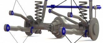
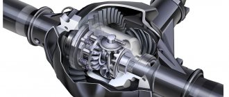
Balancer shaft block with gear drive from the engine crankshaft
The location of the cylinders also plays a significant role in the balance of the internal combustion engine. There are three common schemes:
- Arrangement in a row, when the cylinders are located in the same plane.
- Opposed scheme, when the axes of the cylinders are in the same plane and oppositely directed to each other.
- V-shaped arrangement of cylinders.
The location of the cylinder axes directly affects engine balancing. The in-line design has proven itself well in small-volume 4-cylinder engines. The opposite circuit gives the best balancing performance. The V-shape requires precise angles between the cylinders to achieve optimal balance.
Be that as it may, ideal balance cannot be achieved in any circuit, which is why balancers are installed.
Tags
work of balancing shafts inertial forces. inertial forces second excess inertia and ENGINE engine shafts in an internal engine which engines are used high-power engines stall engine engine balancing. cylinder engines small engine crankcase engine lubrication
articlesmyavtosilu
| Secondary harmonic balancer It was first used in 1911 by Frederick Lanchester to balance four-cylinder engines. Although this device proved to be very effective, for many years rubber mounts were used instead of a damper for reasons of economy. In 1975, the Japanese company Mitsubishi began producing secondary balancers similar in principle to the Lanchester balancer. They are still produced under license by various companies, and engines that use these devices provide much smoother operation. In Fig. Figure 12.16 shows the principle of operation of the secondary balancer. Two balance shafts with offset masses are driven by the crankshaft at speeds equal to twice the crankshaft revolutions. |
Principle of operation
Balancer shafts are installed in pairs on each side of the crankshaft and are complex cylindrical rods. Each balance shaft has a complex geometric shape. The shafts rotate in the opposite direction twice as fast as the crankshaft speed, thereby balancing the second-order inertial forces.
The shafts are installed in the engine crankcase on plain bearings (or needle bearings) and driven by a drive from the crankshaft. The bearings are connected to the engine lubrication system. They are the ones who experience the greatest load during the operation of the shafts. This causes their rapid wear, which is accompanied by noise and vibration.
Drive types
Balancing shaft drive
The most common type of balancer drive is a chain or toothed belt. The drive can also be a gear reducer or a combined version: a gear reducer plus a belt. To reduce vibrations of the shafts themselves, a spring damper is installed in the drive sprocket.
Drive types
Since balancing shafts are designed to balance the crankshaft, their operation must be synchronized with this part of the unit. For this reason, they are connected to the timing drive.
To dampen rotational vibrations, the drive gear of the balancer shafts has springs. They allow the drive to rotate slightly around its axis, ensuring a smooth start to movement of the device.
Most often, a common drive belt or chain is used, mounted on the motor. Gear type drives are much less common. There are also combined modifications. In them, the shafts are driven by both a toothed belt and a gearbox.
Which engines use balancer shafts?
The Japanese company Mitsubishi was the first to use balancer shafts in 1976. The new product is called “Silent Shaft”, which means “silent shaft”.
They are mainly installed on four-cylinder engines with a volume of more than two liters and with an in-line arrangement of cylinders, since it is this design that is most susceptible to vibration and noise.
Balancer shafts are also often used on powerful diesel engines. Now they can be found not only on Japanese models, but also on European and American ones.
Zhor oil
At high mileage, the 2.4-liter engine can waste oil. Replacing valve stem seals is the first repair procedure that owners resort to. In practice, the reason for oil consumption lies in the occurrence of oil scraper rings. The rings are stuck due to savings on oil changes. We should separately mention that on the 2.4-liter engine for Kia, where it is installed longitudinally, oil burns begin due to overheating of the 3rd and 4th cylinders. There, the rings coke quite quickly if the problem with the circulation of coolant in the block is not resolved.
You can select and buy a cylinder block for a Hyundai engine or a Kia engine in our catalog of contract spare parts.
You can choose and buy an engine for a Hyundai Santa Fe or an engine for a Hyundai Sonata in our catalog of contract engines.
Here you can use the links to see the availability of specific Hyundai cars or Kia cars at the dismantling shop and order auto parts from them.
Repair of balancing shafts
Loads on the balance shafts are accompanied by wear of bearings and other drive parts. Repairs are expensive due to their complexity. Therefore, some car owners, instead of replacing or expensive repairs, prefer to simply dismantle the shaft unit. In this case, the fasteners and holes are closed with plugs.
The absence of balancers increases the level of vibration and noise, and the engine balance is disrupted. However, many car enthusiasts assure that vibrations remain insignificant and are successfully compensated by engine mounts. Also, the work of the shafts takes away part of the power of the engine itself. The reduction can reach up to 15 hp.
At the same time, everyone should understand that dismantling the balancer shaft block is a significant change in the engine design and no one can predict how this will affect the operation of the engine and its service life in the future. By deciding on this procedure, the car owner fully assumes all responsibility and risks for its serviceability and service life. The best option would be to replace the faulty part with a new one in a specialized center.
The balancer (balance) shaft is an additional balancing element to reduce engine vibrations. During the operation of the crank mechanism, inertia arises, which becomes the result of the movement of internal combustion engine parts and the influence of a number of other forces.
Internal combustion engines can have different cylinder layouts. The most common:
- In-line diagram, when the cylinder axes are in a single plane;
- The opposed design means that the cylinder axes are at an angle of 180° in two planes;
- V-shaped layout with cylinder axes in two planes;
There are schemes where the cylinder axes are in two planes at different angles, as well as a similar scheme with an additional offset on the crankshaft, etc. The degree of balancing of the internal combustion engine directly depends on this or that scheme. Boxer engines demonstrate the best balance. In-line 4-cylinder engines with a displacement of up to two liters are well balanced. The V-twin engine is optimally balanced only at strictly defined angles between the cylinders.
When an internal combustion engine operates, balanced and unbalanced forces arise. Balanced forces include gas pressure and friction. Unbalanced forces are inertia, weight of the power unit, etc. These forces are called second-order inertia forces.
As you know, balancing is most often achieved by installing counterweights on the crankshaft cheeks. This method works, but does not always allow the engine to be properly balanced, depending on one or another cylinder arrangement.
Inertia arises from the reciprocating motion of the pistons and the rotational motion of the connecting rods. Additionally, there are also inertial forces in the longitudinal plane. The result of the influence of these forces is vibration of the internal combustion engine, which leads to an increased level of noise, certain loads on engine elements, as well as premature wear of parts and mechanisms. To solve this problem, in the design of in-line and other engines, balancer shafts can be used in addition to the flywheel.
The second-order inertial force is balanced by two balance shafts, which may have counterweights. The shafts rotate both at the same speed parallel to the crankshaft and at twice the speed of the crankshaft, which depends on the specific motor.
The balance shaft is a metal rod that has a rather intricate shape with grooves machined into it. The shaft rotates constantly. The shaft rotates in two plain bearings. Lubrication of these bearings is realized through the internal combustion engine lubrication system.
The only way to further reduce internal combustion engine vibration is to balance the unit. An inline four-cylinder engine receives unbalanced forces that arise when masses move, taking into account a particular crankshaft speed. The amount of inertia depends on the volume of the internal combustion engine; as the volume of the power plant increases, the inertia increases.
The balancing shaft is installed on in-line four-cylinder engines with a displacement of more than two liters. It is worth noting that the installation of such shafts leads to a noticeable increase in the cost of the design and is not particularly actively used on cars even in the middle price segment.
Balancer shafts are installed in pairs. They are often located symmetrically on both sides of the crankshaft. The installation location for balancer shafts is most often the engine crankcase, so that the shafts are below the crankshaft of the internal combustion engine. It turns out that these shafts are located under the crankshaft, and the oil pan becomes their installation location.
The balancer shafts are directly driven by the crankshaft. The drive rotates the balance shafts in different directions.
The angular speed of rotation of the balancers is doubled. The drive can be made either separately by means of a gear reducer or chain transmission, or it can be a set of solutions. Torsional vibrations from the rotation of the shafts themselves are damped by a spring vibration damper, which is located in the drive sprocket of the balance shaft drive.
During operation and due to the design features of the drive, balancer shafts are subject to severe loads. The most overloaded bearings are those located on the side opposite to the drive. They wear out quickly, which is manifested by additional noise and the appearance of increased vibrations. In worst cases, the drive chain may break. An additional disadvantage is the power take-off from the internal combustion engine, which is spent on driving the balancer shafts.
The crankshaft is a structure, in short, a piece of iron that is bent many times
The crankshaft consists of main journals located on the same axis, connected by cheeks and connecting rod journals, the number of which is determined by the number of cylinders. Using connecting rods, the crankshaft journals are connected to the pistons.
Depending on how the main journals are located, the crankshaft can be:
- full-support - if the main journals are located on both sides of the connecting rod journal;
- partial support - if the main journals are located only on one side of the connecting rod journal.
Most modern car engines are equipped with full bearing crankshafts.
Basic elements of HF
The main elements include:
- The main journal is the main part of the assembly, which is located on the main bearings (liners) located in the crankcase;
- Crankpin – connects the crankshaft to the connecting rods. The connecting rod mechanisms are lubricated through special oil channels. The connecting rod journals are shifted to the sides;
- Crankshaft cheeks - connect the main and connecting rod journals;
- Counterweights - balance the weight of the pistons and connecting rods;
- The front, frontal part or toe is a mechanism element equipped with a gear (pulley) and gear, and in some cases also a vibration damper. It controls the drive power of the gas distribution mechanism (GRM) and other devices;
- The rear part (shank) - an element of the mechanism connected to the flywheel using an oil deflector ridge and an oil drain thread, performs power take-off.
The back and front sides of the crankshaft are sealed with protective seals. They prevent oil leakage in places where the flywheel extends beyond the cylinder block.
Free rotation of the crankshaft is guaranteed by plain bearings, which are the thinnest steel liners with a special anti-friction layer.
To prevent axial displacement, there is a thrust bearing installed on the main journal (extreme or middle).
Materials for production
The crankshaft is a hard worker that is subjected to strong, rapidly changing loads. Its reliability indicators are determined by the design features and materials from which it is made.
This engine element usually has a solid structure. So the materials for its manufacture should be used as durable as possible, because the stable operation of the system depends on this. The best materials are carbon and alloy steel and high-strength cast iron.
Crankshafts are made by casting, forging steel, and then turning them. Blanks are produced by hot stamping or casting.
The material and production technology depend on the class and type of car.
- For production models, crankshafts are produced by cast iron. This reduces the cost.
- For expensive sports models, forged steel crankshafts are used. This option has a number of advantages in terms of size, weight and strength, and is increasingly used in the automotive industry.
- For super expensive engines, the product is machined from solid steel blanks. At the same time, a decent portion of the material remains in waste.
Design features
Now you know that in addition to serial ones, there are also sports crankshafts.
They make it possible to accelerate the piston stroke at the extreme point of compression, thanks to the special shape of the connecting rod journals. On a standard shaft they are round, but on a sports shaft they are slightly elongated, due to this the engine characteristics change.
Congratulations, gentlemen. Now you know that the crankshaft is not only a heavy piece of iron, but also an irreplaceable part on which a comfortable ride and the service life of the engine and its components depend.
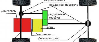
It also provides many of the car’s devices with torque: transmission, generator, cardan shafts, and so on to the wheels.
Of course, you don’t have to tell your girlfriend about this, but tell your motorist friends via social networks. Let them read our blog too - there will be a lot of interesting things.
And see you soon.
Balancing shafts - what are they? What are they needed for? Video
When the crank mechanism operates, inertial forces arise. Their occurrence is associated with moving parts of the mechanism. The following types of inertial forces can be distinguished: reciprocating mass movements and rotating ones. In multi-cylinder engines, inertial forces also arise in longitudinal planes. Simply put, all this creates vibration and noise during engine operation and increases wear on engine components.
To reduce vibrations, the engine is balanced. Most often, when balancing, counterweights are installed on the cheeks of the crankshaft. But this cannot allow balancing the inertial forces of different engine layouts. For example, in-line four-cylinder engines do not balance second-order inertial forces. The magnitude of inertia forces increases with increasing engine volume.
To balance second-order inertial forces on in-line four-cylinder engines with a volume of 2 liters or more, special shafts with counterweights are used, i.e. balancing shafts. The balancing shaft was first used in 1976. Now they are quite widely used by such concerns as Volkswagen, Audi, BMW, etc.
Video
Balancing shafts are installed in pairs on both sides of the crankshaft, usually they are installed symmetrically. But in order to reduce the space taken up, it is preferable to install balancing shafts in the engine crankcase, below the crankshaft. The balance shaft is a complex part made of metal; it usually looks like a rod in which grooves are selected. The balancing shaft rotates in plain bearings, which are included in the engine lubrication system.
The balancing shafts are driven by the crankshaft and rotate in different directions at double the angular speed. The drive can be a backlash-free gear reducer, chain drives or combinations thereof. To dampen torsional vibrations during operation, a special spring damper is installed in the drive sprocket (BMW chain drive).
During operation, more load is applied to the balancing shafts. The bearings furthest from the drive are most heavily loaded. This leads to increased wear of bearings, as well as other elements. All this is accompanied by noise, vibrations, and even a possible break in the drive chain. The consequences for the engine are sad.
Video
Since repairing balancing shafts is too expensive, our craftsmen simply get rid of them. The holes for them are closed with plugs. Engine vibrations increase, but the supports can still cope with them. The use of balancing shafts will naturally complicate the engine design and increase its cost. But that’s not all; when using them, engine power is reduced by about 15 hp.
of your page –>
The engine balance shaft, also known as the balance shaft, is a part of a complex design, the function of which is to reduce engine vibration.
What are balancer shafts
An internal combustion engine is a device of complex design based on the conversion of one energy into another. The more complex the device, in this case, the more cylinders the engine has, the stronger the vibrations and vibrations of individual parts and the engine as a whole are created.
The cylinders in the internal combustion engine are arranged differently:
- In-line engine diagram. This is one in which the axes of the cylinders are in the same plane.
- Opposite scheme. The cylinder axes are on the opposite side, that is, through 180 degrees.
- V-shaped internal combustion engine. The cylinder axes in B-shaped engines are located in different planes.
In all engines there are two types of forces:
- Balanced. Balanced forces are pressure force, friction force.
- Unbalanced. Unbalanced forces are the weight of the power drive, the force of inertia (that is, the reverse force).
Due to the fact that engines cannot operate without vibration, the designers came up with a part that minimizes increased vibration and oscillation values.
The balance shaft is a cylindrical rod with grooves on it. The balance shaft dampens second-order inertial forces. Second order forces in an internal combustion engine are not balanced by installing additional weights on the crankshaft cheek. First-order forces include the mass of the crank, the radius of its movement, angular velocity and angle of rotation. Second-order forces in an internal combustion engine include lambda, that is, the ratio of the crank radius to the length of the connecting rod.
Primary and secondary balancing
Historically, engine designers have used the terms "primary balancing" and "secondary balancing". These terms are related to the order in which problems arise during the development process, and therefore to some extent reflect the importance of these aspects in balancing.
Definitions of primary and secondary balancing vary. In general, primary balancing is associated with compensating the moment of moving pistons (but not their kinetic energy) during crankshaft rotation. Secondary balancing is associated with compensation (or lack thereof):
- kinetic energy of pistons;
- non-sinusoidal movement of the pistons (sometimes part of the primary balancing);
- lateral movement of the crankshaft and balancer shaft;
- various parasitic swings (moments of inertia) created by the balanced masses, such as the unwanted shift of opposing cylinders in a boxer engine created by the configuration of the crankshaft.
Despite the claims of designers and manufacturers, no piston configuration is perfectly balanced. By adjusting some definitions of primary and secondary balancing, it can be argued that some configurations are perfectly balanced within limited limits. Thus, the “in-line six”, V12 and crossplane (that is, a V8 with a 90-degree camber angle, the cranks of which lie in two mutually perpendicular planes) are perfectly balanced by nature, and the boxer engine has ideal primary balancing, since the movement of one part is compensated by the movement opposite.
Operating principle of balancer shafts
Balancer shafts are installed in pairs, on opposite sides of the crankshaft with a symmetrical arrangement. Shafts are mounted on sliding bearings for balancing, which is provided by motor lubrication.
The crankshaft of the internal combustion engine rotates the balance shafts. One balance shaft rotates in one direction, the second in the other. The balancers rotate at a speed twice as high as the crankshaft rotation speed.
Did you know that differential overtension is an indicator of handling dynamics and off-road capability.
Detailed instructions for balancing the crankshaft at home - Automaster
The crankshaft, being one of the most important structural elements of the power unit of any car, is produced using quite complex technologies.
The inevitable presence of technological tolerances and errors in this process, as well as the heterogeneity of the materials used in this process, together with gaps in the interfaces of parts and assemblies, violate (albeit slightly) one of its main operating conditions - balance.
Repair of balancer shafts
During operation of the internal combustion engine, the installed balancer shafts are subjected to heavy loads. The largest share of the load falls on the distant bearings, and therefore, greater wear of the balancing shafts occurs at the joints with the bearings and the bearings themselves. If the load on the balancing shafts exceeds the permissible limit, noise is heard, the internal combustion engine vibrates more, which also causes the balancer drive chain to break.
Full video recording of work in a car service center. Work on removing balance shafts D4CB, Hyundai Grand Starex.
The cost of repairing balancer shafts is quite expensive, and varies from service center to service center. Therefore, many car drivers, in order not to buy new ones or repair them, simply dismantle these balancing shafts and put plugs in the housing holes.
If you use balancing shafts in the engine, this complicates the design and increases the cost of repairs, and also leads to a decrease in the power of the internal combustion engine by approximately 15 hp.
If the balancer shafts are worn out, then, as a rule, engine power decreases and acceleration time increases. This is due to the fact that when the balancing shafts wear out, the phases are disrupted and the valve timing shifts later.
Do-it-yourself modification of spark plugs
The modernization is based on the task of bringing simple spark plugs closer in a number of parameters to the so-called sports spark plugs. Such products are offered by many well-known manufacturers, but they are significantly more expensive.
Sports spark plugs allow you to increase power and reduce consumption; the declared service life of such elements is 70-90 thousand km. mileage However, in practice, the efficiency of their work decreases, on average, after 15 thousand km, and such spark plugs do not last the entire stated period. Taking into account the high cost, buy these elements every 30-35 thousand km. it turns out to be expensive.
It is for this reason that many drivers do not strive to immediately change a set of spark plugs, since there are ways to extend the life of existing ones. The best way to solve the problem is to modify conventional or sports spark plugs.
The procedure is not complicated, so even beginners can handle it:
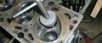
- to make the spark plug work as efficiently as possible, you will need to shorten the side electrode;
- the next step is to correctly adjust the gap on the spark plug;
Now let's take a closer look. Regarding the first point, shortening must be done in such a way that the central electrode is not blocked by the side electrode.
The whole process looks like this:
Used spark plugs are unscrewed from the engine or prepared in advance (you can work with new elements); Next, using a marker or another method (for example, a notch is made), a special mark is applied to the side electrode, which will indicate to what length the electrode should then be shortened. Next, the spark plug is carefully clamped in a vice (preferably with rubber “lips.”) It is important not to overtighten the vice so as not to damage the element. After this, you will need to take a grinding machine and install a cutting disc; Use a tool to shorten the side electrode. In this case, it is important to ensure that the cut is smooth, without bevel. Then the cut site is cleaned with a needle file, nicks are removed, edges are leveled, burrs and other defects are removed. Now you can start setting the desired gap. The value will depend on the type and model of the internal combustion engine. In this case, it is best to use the manual, get the necessary information on specialized automotive forums, etc. Shortening the electrode and setting the gap on the spark plugs must be done with each spark plug, and be sure to maintain the highest possible accuracy (how much is cut off from the electrode and what gap is set). After installing the modified spark plugs on the engine, it is necessary to perform a test run. As a rule, starting should be easier than with conventional spark plugs. Then you can take a trip, appreciating the stability of operation and improved throttle response of the internal combustion engine, as well as better traction at high speeds.
You can also visually evaluate the performance of the candles. To do this, it will be enough to make a test stand right in the garage. For manufacturing you need to have a distributor, a coil and a power source.
Next, the usual spark test is performed, which will demonstrate an increase in spark formation, a change in the color of the spark to a bright blue-red, etc. It is optimal to carry out the check in the form of a comparative analysis, that is, compare the spark, its power and color before starting work (on standard spark plugs) and after (on modernized spark plugs).
If we talk about the modification itself, the simple manipulations described above make it possible to expand and significantly increase the front of the electric spark. In other words, the spark, after removing part of the electrode, is not sandwiched between two electrodes (side and central), but is immediately directed into the combustion chamber.
As a result, the ignition efficiency of the fuel and air mixture in the engine cylinders improves, and subsequent charge combustion becomes more complete. The dependence of ignition on the quality and intensity of spark formation on the spark plug in relation to the composition of the working mixture is also reduced.
In other words, a more powerful spark more easily ignites a rich or lean mixture to varying degrees, which has a positive effect on the overall performance of the engine under load and in other modes. If the mixture is better ignited by a spark, then the flame front spreads more evenly and freely, gasoline burns fully in the cylinders, power increases, and fuel consumption decreases.