Central lock VAZ 2112
The VAZ-2112 central lock is considered a fairly safe device for the owner of this car. Keeping pace with progress, a person strives to be in time everywhere. This type of transport, such as a car, has long become not a luxury, but a means of transportation. According to statistics, every second person drives a car.
Does not work
The central locking motor may not work for a number of reasons:
There was a break in the winding near one of the poles.
If the supply voltage is applied for more than one second, the collector will heat up and after the end of movement, the hot collector leads to the melting of the plastic under its plates. Because the brushes are spring-loaded, they begin to connect, squeezing out the molten plastic, and when the brushes connect, the central locking power fuse burns out (after which the activator rod stops moving even manually). Often the reason for this is cheap alarms (for example, there is not enough time for the central locking system to close completely) and the cold season.
Overheating of the motor due to constant opening/closing in a short period of time (30-40 seconds).
Worn collector plates. In this case, the central locking does not always work, but every other time. The lubricant thickened, or the plastic was squeezed out from under the plates to the top due to the high pulse duration, and the collector overheated.
Where is
The block under the dashboard is approximately opposite to the right near the driver’s right knee, probably it can be called behind the display block. You'll have to unscrew the protection on the gas pedal and stick your hand high.
The fact is that all drives are connected in parallel. And if one does not work due to a block, then all the doors will not work. There remains a place for the standard twist in the threshold at the front near the driver's pillar, where the wires go into the door, the transition itself from the pillar to the door and the wires into the door.
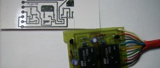
Scheme
1 - mounting block; 2 - 8A fuse; 3 - control unit; 4 — gear motor for locking the lock of the right front door; 5 — gear motor for locking the right rear door; 6 — gear motor for locking the left rear door lock; 7 — gear motor for locking the lock of the right front door; A - to power supplies; B - diagram of conditional numbering of plugs in the control unit block; C - scheme for the conditional numbering of plugs in the blocks of geared motors for locking locks
Malfunctions
Inability to control the doors from the driver's door.
There is no power to the central locking control unit.
Burnt out or poor contact in the outboard fuse holder.
The fuse is connected to the wiring running behind the mounting block.
Source
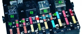
VAZ 2112 fuse diagram
With an 8-valve and 16-valve engine, it is equipped with a main mounting block, and since 2008 an additional console has been added. A diagram with element markings is printed on the left side of the main block cover and placed below.
The designations of all elements are presented below. You can find the transcript in the table.
| Circuit breakers | Power, A | What protects |
| F1 | 5 | Lamps for turning on the license plate lighting, instruments, side lights, trunk, left side. |
| F2 | 7,5 | Low beam |
| F3 | 10 | Further |
| F4 | 10 | PTF |
| F5 | 30 | Door windows |
| F6 | 15 | Portable lamp (socket) |
| F7 | 20 | Engine cooling fan. Sound signal. |
| F8 | 20 | Rear window heating element. Relay for turning on the heated rear window. |
| F9 | 20 | Recirculation valve. Cleaners, windshield and headlight washers (wiper fuse). Relay for turning on the heated rear window. |
| F10 | 20 | Spare |
| F11 | 5 | Starboard side marker lamps |
| F12 | 7,5 | Middle left |
| F13 | 10 | Far left. Power indicator lamp |
| F14 | 10 | Left PTF |
| F15 | 20 | Electrically heated seats. Trunk lock lock |
| F16 | 10 | Turn signals and emergency lights. |
| F17 | 7,5 | Interior lighting. Ignition switch. Stop signal. Watch. |
| F18 | 25 | Glove compartment lighting. Heater controller. Cigarette lighter fuse. |
| F19 | 10 | Locking door locks. Relay for monitoring the serviceability of brake light lamps and dimensions. Direction indicators. Reversing light. Generator excitation winding. On-board control system display unit. Instrument cluster. Watch. |
| F20 | 7,5 | Rear fog lamps. |
Relay
- K1 - lamp health monitoring;
- K2 - windshield wiper;
- KZ - direction indicators and emergency lights;
- K4 - switch on low beam;
- K5 - high beam;
- K6 - additional relay;
- K7 — heated rear window;
- K8 - rear PTF.
Starter fuse and relay
Installed on the device itself between the engine and the fan radiator. If signs of a malfunction appear, it is better not to delay replacing the element and install a new relay.
Fuel pump fuse and relay
Located in the additional interior installer - No. 3. Responsible for the fuel pump relay No. 5.
Relay and fuse for cigarette lighter
No. F18 is rated at 25 Amps.
Stove
The 25 A element F18 is responsible for protecting the operation of the electrical circuit of the heater motor.
Turn signals
The elements are marked as F19 and are rated at 10 Amps.
Brake lights
Located in the main block - No. F17. Its power is 7.5 A.
Where is the alarm fuse located?
No. F16 and rated 10 A.
Cooling Fan
The F7 element with a power of 20 Amperes is responsible for its protection.
Which fuse goes to the radio?
This is an F4 rated at 20 A.
Window lifters
F5 at 30 A.
Fuse and relay for central locking VAZ 2112: where is it located
They can be found in a separate box behind the main mounting block.
Ignition
The main relay is located in the additional cabin unit, where it is number 6.
Reverse
F19 with a rating of 10 Amperes is responsible for the lamps.
Fogs
Protected by three inserts: right - F4, left - F14, and rear - F20. The power of all PTFs is 10 Amps. In case of tuning, you may need to replace them with new ones along with the fog lights. The connection occurs via switch K8.
Lamp health monitoring relay
Marked as K1 in the main block of the VAZ 2112.
Brake
Installed under the brake pedal.
Relay and fuse for injectors
The additional element F3 is rated at 15 Amps.
Fuse for interior light
The F17 element with a power of 7.5 A is responsible for the safe operation of the VAZ 2112 interior lighting lamp.
Number plate illumination
Corresponds to F1 with a rating of 5 Amps.
Generator
A three-level relay voltage regulator is located on the device. It is better to replace the factory element with a new one, since three-level voltage regulation often leads to a short circuit.
Heated rear window
Relay K7 is responsible for turning on. Protects the F8 electrical circuit with a rating of 20 Amps.
Seat heating
It is protected by a 20 Amp F15 insert.
Wiper relay
This is a K2 and without its stable operation there will be no washer supply to the windshield, and the wipers will not be able to do their job.
Charger
They placed it next to the device - one of the few elements of this kind under the hood of a car.
Low and high beam VAZ 2112
It is protected by fuses F2 and F12 (left and right headlights), and the high beam is protected by F3 and F13 (left and right). The first has a rating of 7.5 A, and the second has a rating of 10 A.
Fuse for the dashboard of VAZ 2112
Located in the wiring harness leading to the instrument panel from the battery.
Dimensions
There are 2 fusible elements - F1 and F11, left and right. The power of both is 5 Amperes. Factory fuses require replacement due to the fact that the dimensions often burn out due to their malfunctions.
Heated seats
It is protected by an element marked F15 for 20 Amperes.
VAZ 2112 speedometer fuse: where is it located?
He's gone.
Opening the trunk
This is an F1 and is rated at 5A.
Fuse F6
Responsible for protection against burnout of the car socket. Its rating is 15 Amperes.
VAZ 2112: fuse F17 blows
Most often, this element, which is responsible for interior lighting, fails due to a battery failure. Its power is 7.5 A.
Fuse F19
Responsible for protecting the brake light, reversing lights and dimensions.
Relay K1
An element of lamp serviceability, which in older versions is replaced by a jumper.
Relay K6
This is a reserve item.
Speed sensor
Located on the wiring harness leading to the device.
Why the central locking on the VAZ-2112 does not work: the main reasons
Central locking, or “CZ” as it is briefly called, is a necessary and essential thing for any car, allowing the owner to open and close any door in the car with just one movement of the hand. However, it happens that this system ceases to function completely, or its individual parts do not work properly.
There are reasons why one or another part of the central lock may fail, and we will discuss each in detail below.
What is the central locking on the VAZ 2110?
The purpose of this type of device is to centrally control the automatic mechanism for opening and closing all doors in the car at once. This is especially convenient for working in conjunction with an alarm system and when operating a car in general. However, the reliability of the operation of the central locking system should definitely be checked every time by moving the handles of all four doors before going about your business for a long time, since the actuator can often fail and one of the doors may remain unlocked.
Structurally, the VAZ 2110 central lock consists of the following elements:
- electronic transistor control unit;
- gearmotor actuators, also known as activators (one for each door);
- a limit switch that determines the current state of the door (open or closed);
- electrical wiring and other installation elements.
Central locking diagram for VAZ 2110
The central locking does not work: signs of malfunction and causes of their occurrence
It happens that when the central lock located on the driver's door is closed, no action occurs on the other doors. However, as soon as you move it a little, the doors immediately closed. It is immediately clear that the problem here is the presence of malfunctions in the central locking and several reasons contribute to this.
Among all the possible causes of malfunctions, all the most basic ones can be identified.
No contact in the drive
With such a malfunction, the contacts inside the control drive do not close the necessary contacts in time. This happens for several reasons:
- The adjustment of the rod that connects the lock button and the drive is done incorrectly. This reason contributes to the incorrect position of the rod and lack of contact with the electric drive.
- The button touches part of the casing and does not allow it to lower to the required depth to ensure contact of the traction with the electric drive. Despite the fact that the driver's door closes, no signal comes to the other doors.
Check the condition of the metal rod.
When such problems occur in the operation of the central locking, first of all you need to make sure that the button is lowered to the very end. If for some reason this does not happen, first inspect the casing for burrs, and then inspect the rod for its even and accurate position.
Fuse blown
If manipulations with the central locking rod do not bring any results, and they do not react in any way to either opening or locking, then first of all you need to check its electrical circuit, and specifically the fuse. Because on the central lock it can fail not only if a short circuit occurs in the circuit, but also if the slightest overload occurs.
The central locking fuse is indicated by a marker.
Overload occurs most often from insufficient position of the rods, as well as lubrication in them during winter operation of the car.
The central locking wires are broken
Broken wires are not the main reason, but one of the reasons for the failure of the central locking system. The main reason for this is the break in the wires in those places where they bear the greatest load. Such a place is definitely the passage of the corrugation from the side of the pillar and the driver's door. And since it is the driver’s door that is most often opened in any car, it receives most of the load.
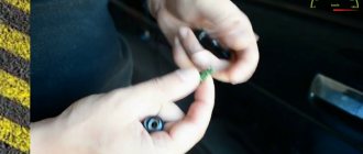
- It is quite easy to identify such a malfunction; you just need to release one of the ends of the corrugation through which the wires pass into the door and pull one of the five central locking wires. As a rule, they are connected into one bundle, or go next to each other.
- After carrying out such manipulations, a wire that is torn or broken will easily give in among the general heap.
- If you are absolutely sure that a particular circuit is faulty, replacing it will not be difficult by inserting the required wire and further insulating it with electrical tape.
- When the wires are broken or torn in other places, the fault can only be found by testing the circuit with a multimeter.
Block burned out
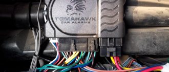
Another reason why the central lock may fail is a burnout of the central locking unit. And in order to diagnose it, you need to use the above-mentioned multimeter and determine the presence of voltage at the contacts of the block.
This is what the immobilizer and central locking unit look like behind the instrument panel.
Please note that during diagnostics it is necessary to operate the lock in the driver's door so that impulses are sent from it to the main unit.
The central locking activator is faulty
And the last reason why the central locking refuses to work is the failure of the activator on the central drive. It can fail both for mechanical reasons, due to wear of rubbing parts, and due to the influence of external factors of moisture and corrosion.
If the activator itself breaks down, it is necessary to replace the electric drive with a new one and replace it. Pay attention to the fact that the drive must have five wires of different colors.
Problem in the operation of the central locking electrical circuit on VAZ cars
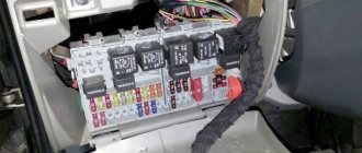
The first possible problem follows smoothly from those mentioned in the previous section. Overload in the operation of activators leads to an increase in the operating current in the supply circuit above the rated value. As a result, the fuse blows and the central locking of the VAZ 2110 simply “dies”.
It is by checking the fuse that the diagnosis of central locking malfunctions begins. By the way, it is located in a very specific place and it is not easy to find it right away even if you know where to look. In order to get to it, you will need to fold back the central panel with the fuses and dig into the entire wiring harness in the niche that opens behind it. The “comrade” you need is packaged in a special plastic cup and connected to the pink wire.
Central locking unit VAZ 2110
Another very common and obvious problem is the central locking connector. It is located in the most unfavorable place for this in the interior body, under the foot mat. A large amount of moisture and dirt inevitably gets there. Electrical contacts are intensively oxidized. As a result, the power supply circuit involuntarily breaks at the point where the plug connector is connected.
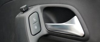
The principle of operation of the central lock on the VAZ-2112
The central lock, which operates from the driver's door drive of the VAZ-2112, works as follows:
- The electric drive installed in the door is designed not only to control the lock, but also to issue a signal to the central locking unit. He, in turn, transmits commands to other doors to open and close the doors.
- In order for the driver's door drive to be so multifunctional, it has as many as five wires, unlike standard drives with two. Additional channels are intended for communication with the central locking control unit.
Drive for driver's and passenger's doors.
When the lock closes, the rod on the driver's door moves down, thereby closing certain contacts on the electric drive. From these actions, the central locking unit receives signals and transmits commands to the drives of all other door locks . Their discovery occurs in the same way.
Source
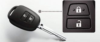
Basic operation of the central lock
- Unlocking is done by opening the driver's door lock with the key.
- The design provides for unlocking the remaining doors by passengers at their own discretion.
Central locking does not lock doors
- Each door of the vases is equipped with separately mounted gear motors, connected to the locking rods.
- The gearbox consists of a direct current electric motor, and the excitation is produced by permanent magnets driving rack gears.
- The gearmotor design has a switch on the driver's side that is activated when the locking latch is pressed or the key is turned in the door lock.
- When the contacts of the switch are closed, the signal is sent to the electronic control unit and all gear motors located in the doors are switched on.
- They activate the rods, which in turn use levers to lock/unlock the doors.
- The design of the control unit provides for automatic unlocking of all door locks during a traffic accident (impact on an obstacle).
Causes of failure and their correction
If the central locking fails and does not work, you need to check:
- fuse (see VAZ 2110: how to replace fuses);
- wires, connectors;
- central control unit;
- operation of gear motors.
Note: a failed control unit and gear motors cannot be repaired, so they must be replaced with new units.
- If the central locking breaks down, it must be repaired immediately.
- It is not difficult to identify the cause of its failure, and in many cases it will not be difficult to carry out repairs yourself.
- If reasons of a more constructive nature are identified, it is necessary to replace its assembled parts.
The complete central locking structure consists of:
- activator – electric drive;
- electrical wire terminals;
- drive rods.
Connecting the central lock
Lock failure is most often due to failure of small parts. The electric drive is installed from various suppliers. Parts may have slight differences in the applied forces and design features. But the work they produce does not make much difference.
Why the central locking on the VAZ-2112 does not work: reasons, repair
A week after the purchase, my Central Locking (CL) started acting up. At first, the alarm did not lock the car, I locked it with the key. And after a couple of days everything was completely covered.
We had to get into the car “the old fashioned way” and lift all the bolts in order to let anyone into the car. In general, it’s not very stressful, but maybe I’m wet myself, or maybe the 21st century outside is making itself felt. Having found some free time on Sunday, I drove off to a friend’s warm box and, according to the “Law of the Garage,” stuck there for the whole day.
Some of the photographs and diagrams were taken from the Internet.
To begin with, armed with a diagram, I looked at what awaits me and where the roots grow from. In general, everything is quite simple. 1. Mounting block.
2. 8 A fuse. 3. Control unit. 4. Right front door locking motor. 5. Motor reducer for locking the right rear door. 6. Left rear door locking motor. 7. Motor reducer for locking the left front door with a contact group. A - to power supplies; B - conventional numbering of plugs in the control unit block; C - conventional numbering of plugs in the blocks of geared motors for locking locks. The search for the fuse was not crowned with success for me, it was decided to check the wiring and not waste time. Finding the central locking control unit is also not so easy, it is located near the ECU at the feet of the driver and passenger behind the radio, if you are a gymnast, then removing it will not be a problem, and I refreshed my memory of the entire Russian vocabulary while I was removing it.
Using a 10mm wrench, I unscrewed the nut on the right side and left it on the stud on the left. It’s very inconvenient to remove. I took it off and smelled the relay. Seems normal. I took it apart, nothing burned was visible, the contacts were not oxidized. It's unlikely that it is. I called the store out of interest, the price tag of the relay is about 1400 wooden ones. The idea of checking another relay went away by itself))) I decided to dig in the opposite direction. I took off the driver's door trim, put the cartoon in my hands and go ahead and call the wiring according to the diagram. From the mounting block on chip “No. 1” there is a pink wire with a constant positive, there is 12V, we move on. The ground is ringing, which means the problem is not in the power supply. The wires between the activator and the central locking control unit are ringing. All is good. The activator current remained. I applied voltage, the activator worked every other time. Yeah) Maybe this is the villain.
A drill will help me) I clamped the activator in a vice, drilled out the rivets and disassembled it.
Basically, 2 gear wheels that open and close the door and a three-pin microswitch that sends a signal about opening or closing to the control unit, which gives a signal to other activators. I didn’t feel like running to the store and after calling about the relay I decided not to play with fate and restore old activator. We found a regular activator and took it apart. The motor costs the same. He will be the donor.
I quickly took it out, re-soldered it and put everything in place. Everything worked. I spent almost the whole day on such a small thing, but it’s still not clear why the tsz started working, because mechanically I blocked the contact. Maybe the wiring is a bit messed up, but fortunately everything works. The whole issue regarding the central lock remained resolved. I think someone will find this thread useful)
The VAZ-2112 central lock is considered a fairly safe device for the owner of this car. Keeping pace with progress, a person strives to be in time everywhere. This type of transport, such as a car, has long become not a luxury, but a means of transportation. According to statistics, every second person drives a car.
Contents Doesn't work Where is it Diagram Faults
Let's make the alarm system and central locking together
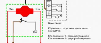
Any modern alarm unit is equipped with two relays connected to the central locking control unit. One relay is opening, the second is locking, and the circuit in the general case looks like this:
Control of central locking by supply of “mass”
In our case, the green and white cords coming from the signaling unit will be required, as indicated in the diagram. However, they will not be the only ones needed. We will connect the relay contacts to breaks in the standard wiring. This means there will be not 2, but 4 cords.
Connection diagram for VAZ central locker
Take another look at the diagram published in the first chapter. We will connect the relay to the gap in the white and brown wires going from the microswitch to the central lock control unit. And it is obvious that it is easier to break these wires near the 8-pin connector. The same one shown at the beginning.
To avoid any questions, we will show you what should happen as a result:
Connection diagram, central lock VAZ
The common contacts are connected to the wires coming out of the microphone. The white cord continues with the brown wire coming from the door, and so on. Normally closed contacts are also used, along with normally open ones. These are the features of connecting to the VAZ central locking system.
An approximate sequence of actions performed by the installer:
- Make and lay a 4-core cable running from the signaling unit to the 8-pin connector;
- Connect the cable on the side of the alarm unit (see the last diagram);
- Near the 8-pin connector, disconnect the white and brown wires coming from the microswitch (pins 5 and 7). The main thing is not to confuse them with the wires going to the triangular connector “C”;
- Make connections to the broken wires, white and brown. That's all.
We have given this sequence to emphasize once again that the relays are switched on between the microphone and the central lock control unit. There is no need to connect any additional devices. As a result, the alarm system will be able to control the state of the locks.
Remember that installation is performed by removing the negative terminal from the battery.
All wires added to the car structure must be protected (use heat-resistant tubes or electrical tape). Twisting is not the worst method to connect two wires. But it's even better to use soldering.
An interesting nuance from practice
It would seem that if a person has experience working with electrical equipment, he can do everything according to the instructions given. As a result, if no mistakes are made, you may encounter an interesting phenomenon. Instead of closing, there will be a short-term locking followed by opening. And vice versa. What to do in this case?
Take a look at what exactly may be present in some of the configurations:
Cheaper - no driver actuator
The driver's door may not have an actuator. And then, it is useless to connect the signaling system to the control unit. There is no actuator, which means there is no one to close or open the door and move the microphone lever. Let's say the locks are closed, and then we remove ground from the brown wire and we get the following: the white wire is on ground, unlocking occurs.
We note the following: installation can only be carried out when you are sure that there is an actuator in the driver's door.
There were configurations where only a microswitch was installed. There is no need for arrogance here - adding an actuator will be difficult, since standard wiring must go to it. As you understand, it may not be available from the factory. And it’s unclear what to do then.
There remains one unanswered question - where exactly the central locking control unit is located. In these VAZ models, if there is a central locking system, then there is also a control unit. And it is located under the torpedo cover, next to the driver, on the right:
VAZ-2110, BU TsZ
We remove the “beard” of the torpedo and look at what is on the upper right. On the same plane with the radio connector there are two boxes attached - the one we need, as well as the immobilizer (if there is one).
We would be lying if we did not say that in reality there is another option for installing the alarm. Standardly, only two power cables go to the actuators. Having a power outlet equipped with a fuse, these cables are connected directly to the alarm relay. This option, as you might guess, is not recommended. Imagine what would happen if the alarm system broke. The central lock must remain, but in this case this will not be done. Happy connection!
Does not work
The central locking motor may not work for a number of reasons: The winding has broken near one of the poles.
If the supply voltage is applied for more than one second, the collector will heat up and after the end of movement, the hot collector leads to the melting of the plastic under its plates. Because the brushes are spring-loaded, they begin to connect, squeezing out the molten plastic, and when the brushes connect, the central locking power fuse burns out (after which the activator rod stops moving even manually). Often the reason for this is cheap alarms (for example, there is not enough time for the central locking system to close completely) and the cold season. Overheating of the motor due to constant opening/closing in a short period of time (30-40 seconds).
Worn collector plates. In this case, the central locking does not always work, but every other time. The lubricant thickened, or the plastic was squeezed out from under the plates to the top due to the high pulse duration, and the collector overheated.
Where is
The block under the dashboard is approximately opposite to the right near the driver’s right knee, probably it can be called behind the display block. You'll have to unscrew the protection on the gas pedal and stick your hand high.
The fact is that all drives are connected in parallel. And if one does not work due to a block, then all the doors will not work. There remains a place for the standard twist in the threshold at the front near the driver's pillar, where the wires go into the door, the transition itself from the pillar to the door and the wires into the door.
Scheme
1 - mounting block; 2 - 8A fuse; 3 - control unit; 4 — gear motor for locking the lock of the right front door; 5 — gear motor for locking the right rear door; 6 — gear motor for locking the left rear door lock; 7 — gear motor for locking the lock of the right front door; A - to power supplies; B - diagram of conditional numbering of plugs in the control unit block; C - scheme for the conditional numbering of plugs in the blocks of geared motors for locking locks
Malfunctions
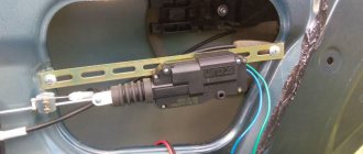
Good day everyone. In my last post I asked you for help and advice on repairing the central locking. Thank you all for your comments and responsiveness. Today in this post I will tell you how this problem was solved. So, initially the problem was that the car was armed, but the locks did not close. They also couldn’t be closed by manual pressing. It was decided to take everything apart and look. During disassembly, I found out that the driver’s door has a regular two-wire actuator, instead of the required 5-pin one. The remaining three contacts went to the lock itself; these were wires to the limit switch for the open/closed positions.
Full sizeThis is the actuator
Full size Here is the wiring to the central locking system, red and yellow are to the actuator, they alternately receive a signal depending on the position of the limit switch, the black wire is ground, and white and brown just transmit a signal about the position of the lock
Well, everything seems to be working at this stage.
Forcibly applied to the actuator. short-term
+12V, short-term, otherwise there will be an overload and it will either burn out or the brushes will close. He's twitching, which means he's alive. I went further to look for the reason.
I thought that the wires might have frayed in the place where they enter the door. He pulled out the bunch, and for good reason. Some wires had broken insulation - I fixed it with electrical tape.
Full size If you look closely, you can see exposed veins.
Let's go further, I read that there is a central locking control unit. We need to find him now. I opened up the floor covering to see where the beam went.
As a result, I found the end under the heater on the driver's side of the connector and on it a circuit rewound with electrical tape. Even then I felt that there was probably a problem with it, but out of ignorance, I continued my search further.
Full size Here is the old central control unit. As you can see, there are 6 wires coming here. Pink 12V, black ground, white, brown, yellow, red - I described them above. Here is the entire detailed wiring diagram, the colors matched.
Full size Central locking diagram for VAZ 2110, relevant for VAZ 2111 and VAZ 2112 In the end, I realized that all the signals reach this unit, there is power to it - but there is nothing at the output. That means it’s still dead. After shopping around, everywhere they offered me an 8-pin block, and only on the fourth day did luck smile on me and I bought the original 6-pin VAZ 2110 central locking block. It was immediately installed in its place, and I pressed it with bated breath signal - and hurray! closed, opened. Everything is as it should be!
Full sizeOld and new central locking blocks
Full size The connectors of the old and the new are identical. Well, since I’ve already taken apart a lot of everything, at the same time I tightened up all the masses. I also found two free two-pin chips in the same place in the driver’s feet under the stove. Maybe someone knows what they are for.
Full size Here they are in the distance, yellow and green, and purple and green, what kind of chips are they, tell me)
The well-known system, called central locking, as a rule, is not installed on all VAZ-2110 cars. Central locking is needed to simultaneously lock all car doors. This system is very convenient for the car owner. With one key you can control all doors. But, unfortunately, even such a system tends to break down. A large number of VAZ-2110 car owners face this. There are several reasons why the central locking may stop working or function incorrectly:
- Providing long or frequent pulses to control the opening or closing of doors.
- Central lock fuse is faulty.
- The plug connector has oxidized.
- Malfunction of the central locking control unit.
So, in order to understand the reason for the malfunction of the central locking, you first need to know what it consists of:
- electronic transistor control unit;
- actuators of the gearmotor (activator);
- limit switches;
- electrical wiring.
How well do central locking and alarm systems work together in VAZ-2110 cars?
As you know, a modern alarm system involves autonomous control of all opening parts of the car. For this reason, it is possible to connect the VAZ 2110 central locking system to the alarm system. The connection diagram for the signaling device is included in the operating instructions for the device. The central locking control circuit also seems to have an additional unused connector for this purpose.
However, in reality it is not so simple. Control signals from the alarm system to the central locking system will conflict with the information received from the limit switch installed in the driver's door. For this reason, the standard central locking control circuit with which VAZ 2110 cars are supplied from the factory should be slightly altered.
Problems with central locking: reasons
Today, incorrect operation of the actuator is not uncommon. This problem is encountered quite often by owners of VAZ-2110 cars. But, much to our surprise, this problem can actually be dealt with without the intrusion of third parties. There is no need to look for a highly qualified specialist in the field of car electronics repair to fix the breakdown; it is easy to do it yourself if you wish. The first reason why the central locking system may fail is the fuse. Before you start disassembling the interior of the car, in order to understand the breakdown, you need to check the fuse. The second possible reason is that there is no contact in the drive. This is perhaps a common problem among central locking mechanisms. Another aspect of the malfunction can be broken wires. Also, the central locking system sometimes fails due to the control unit, which for one reason or another burns out. And finally, the reason why the central locking failed is a malfunction of the activator. The most important task of the owner of a VAZ-2110 car is to look for a breakdown of the central lock along the chain, starting with the fuse and ending with the control unit (CU).
Sensors in the central locking also often fail. Replacing them is quite easy. Every car owner can do this independently.
Since the car alarm is often closely connected with the lock, it is worth starting the check with this element. First you need to open and close the lock of the front left door using the key. If the central locking system works, it means that the alarm system has failed.
It is worth knowing that one of the main reasons for the lock mechanism to malfunction is a device called an activator. It is installed in the front doors of the car. Its main function is to send an electrical signal to all doors.
Problems in the operation of the activator electric drive
The central locking actuator is quite fragile and does not tolerate overload. The activator body, made of plastic, can easily melt if the frequency of door closing is excessively high. The duration of the control pulse also plays an equally important role. Try to always remember about the extreme fragility of the activator and not to load it during operation.
It is easy to guess that the activator is located in each individual door of the car. If the body of one of them melts due to overheating of the electric drive commutator, this becomes the cause of many problems:
- the activator on individual doors stops functioning;
- Constant overloads in a jammed electric drive cause the fuse to fail.
The central locking of the VAZ-2110 does not work
If the situation is completely hopeless in repairing the central locking, then in this case you can try to purchase new mechanisms and install them yourself. In this way you can significantly save your own money. Central lock installation:
- disconnect the battery and remove the door trim;
- dismantle window regulators;
- remove old activators.
After carrying out the above steps, new activators should be installed. In order for new drives to work correctly, a lot of space is needed for free movement of the rod. Activators must be mounted on a flat surface so as not to impede the operation of the gear shafts. Before installing the drive in the door, you need to bend the rod correctly so that the bend angle is minimal. After installing the above element, you need to lay wires from each door to the place where the control unit will be mounted. The wires must be laid at the bottom of the door so that they do not collide with any moving mechanisms of the doors or body. The next step is installing the block. The control unit must be placed either in the car door or behind the instrument panel so that intruders do not have access to it. The place where the control unit (CU) will be installed must be dry. After installing the control unit, the next step is connecting the central locking wiring, which comes with the system.
Source
Problem with the operation of the VAZ-2110 central locking control unit
Electronics, of course, are reliable things. Modern control modules for the central locking VAZ 2110 are assembled using a transistor control circuit. This eliminates their mechanical wear. The shelf life of key components is measured in tens of years. The control unit is located under the plastic dashboard cover on the right side of the driver's seat.
However, power transistors can easily fail when the activators are overloaded and the collector is short-circuited. It may even happen that the signal from the control unit will constantly be sent to the lock drive if the transistor is broken. Otherwise, it will simply not turn on.
Checking the control unit is extremely simple. The voltage from the negative terminal of the battery, or directly from the pink wire supplying the control unit, is supplied to the contacts of the gearmotor (activator) in series to the red and yellow conductors. All of the above contacts can be found directly on the eight-pin connector of the control unit.
Thanks for subscribing!
Also, the control unit may issue erroneous control commands due to incorrect operation of the limit sensor. Being a mechanical device, the main door switch can simply wear out. As a result, the control unit simply will not be able to function correctly, since it will not know in what position the car doors are currently located, whether the driver's door lock is closed or open.