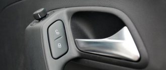
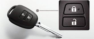
In order to protect your car from theft, you can equip it with a device such as a central electronic lock. To do this, it is not at all necessary to contact a service or specialized workshop, because in fact, its installation is much simpler than it seems at first glance. In today's article we will talk about how to install central locking on a VAZ 2114 and how to avoid possible mistakes.
Alarm system with central locking VAZ 2114
Introduction
I went online to search for information on how people connect these Chinese units to a VAZ and came to the conclusion that everyone installs such units in a terribly artisanal way, removing half of the wiring, adding some of their own, and in the end, all this does not “successfully” work. Among the makeshift connection instructions, I came across the only normal article by Soliderus, who installed a similar control unit on his Chrysler; his article helped me a lot. But since we have a harsh domestic auto industry, we had to invent our own connection diagram, but first things first.
Please read this entire article first before disassembling the machine; you may not have any parts on hand or may be missing some of the original wiring.
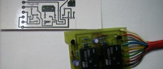
Used kit
The kit is small and is pictured in full below:
Used kit
The kit also includes instructions in English:
Instructions - description of the control unit
Connection diagrams
Theory
Before starting the installation, I want to warn you about the characteristics of my particular VAZ 2114 car (2006 model year, “Lux” equipment, the wiring under the dashboard is numbered as “VAZ 2115-...”), since I myself, from personal experience, have seen “four” and “tags” of the same year of manufacture, the same configuration, but with completely different wiring (I assume that this was due to different supplies of wiring to the conveyor).
After looking at the information on the Internet, I came to the conclusion that the overwhelming number of people install the control unit according to the wrong diagram “D”, from the instructions, which will not fit the Samar family (VAZ 2108/09/99/13/14/15) , since the opening and closing of doors (or rather, the supply of a signal to the BUDU (Door Lock Control Unit)) in Samara is controlled by a “minus”, and according to the “D” scheme, control occurs by supplying a “plus” to the BUDU. As I found out, this scheme only works when the standard BUDU is removed and the BU works every other time and only one button on the control key works. In my case, when connecting circuit “D” (I tried to connect it together with the BUBD), I burned several fuses and started looking for another connection method.
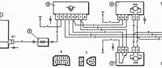
The scheme we need and works is scheme “C”
Scheme C
According to this scheme, our control unit will send a “minus” signal to the BUDU and everything will work normally, without removing the BUDU itself.
Installation
To begin with, I determined which wires in the control unit block I needed and which I did not. I didn’t need: - green wire - window closer; — blue wire — trunk opening; — pink wire — siren (there was a siren, but I just didn’t want to install it); Also, orange and orange-black wires are not needed, since according to scheme “C” they are not needed.
We still have: - red - “plus” 12v to the battery; — black — “minus” 12v (I connected the minus to the body, since the control unit does not necessarily require a minus power supply from the battery); — yellow and yellow-black — connect to the negative (I connected them to the main negative and all 3 wires to the body); - 2 brown ones - they supply a plus to the alarm button (some people connect them to the dimensions); — white — it sends a minus for closing; - white-black - it sends a minus to the opening.
For clarity
Used block with signatures
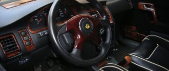
The control unit was installed on self-tapping screws, on the lower plastic part of the panel (to the left of the steering wheel height adjustment lever, next to the hood opening handle), but you can install it as you wish.
Plus, I stuffed it into the cambric and passed it through the rubber of the headlight range control, making a small hole with an awl (I couldn’t find a more convenient place, without drilling, in the whole car):
Positive wire
Under the hood I connected the plus directly to the standard terminal, tightening the bolt to “10”:
Positive terminal
I started connecting the emergency lights. I read on the Internet that you need to disassemble the hazard warning button, solder something, short circuit something, and in general it turns out that this round button interferes with normal steering and everywhere they show how to redo it. In general, I did not find a complete pinout of the button; with the help of a general electrical diagram and the scientific “poke method” I found out that:
— blue-black wire — left turn; - blue wire - right turn
Hazard warning button block
I again stuffed the two brown wires into the casing and brought them to the emergency flasher button block, pulled out the blue-black and blue wires from the block, using a small awl and “someone’s mother,” and soldered the brown wires directly to the “mother” terminals, so how I didn’t want to cut off the factory terminals (you don’t need a lot of tin, because if there is a lot of it, the terminals won’t fit back into the block):
Emergency signal block with soldered brown wires BU
Removing the BUDU turned out to be not an easy task; it is located above the hood release handle, almost under the dashboard, in general in not the most convenient place.
I have installed BUBD 21093-6512010-03 NPO Itelma.
BUBD 21093-6512010-03 NPO Itelma
This BUBD was installed on all Samara II (VAZ 2113/14/15), I’m not sure about the Samar I (VAZ 2108/09/99), check whether the BUBD is the same on your car, because the pinout may be different. The wires we need in the BUBD block are: - brown - closing the doors; — blue — opening doors By analogy with the emergency gang, I soldered the wires to the terminals according to the diagram: — brown from the BUBD with white from the control unit; — blue from BUBD with white and black from BU
BUBD block with soldered wires from the control unit
Now the most interesting part is the driver's door.
We remove the door trim, remove the black “anthers” from the inside.
There are several options:
Option 1) You have a certain “microswitch” in the driver’s door, which, when you open the driver’s door with the key, sends a signal to the ECU and it opens the other doors (another name for such a switch is central locking, since without such a switch you would have to close each door separately). The driver's door motor is missing. There is also a block with two wires in the driver’s door: one is red, the other is yellow (the same blocks are 100% in the other 3 doors of the car) they supply power to the electric motor, which opens/closes the door lock.
Option 2) Everything is the same as in point 1, but the block with the red and yellow wires is missing (a very common situation, especially if the equipment is not “Lux”). In this case, you need to pull these wires from the ACU to the driver's door (the diagram of the door lock system will be below).
Option 3) You have/have had a non-standard alarm installed and now you have more wires in the driver's door than in the entire car. Here I can’t tell you anything, since I myself have not installed a non-standard alarm system in Samara, try to figure it out using a diagram of the door lock system.
Shown here is an unmodified VAZ 2114/15 (may be the same as the VAZ 2109/99):
Door lock system diagram
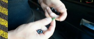
We have the first scenario, which means we must first remove the “microswitch”.
Microswitch
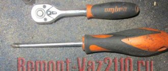
How to remove it is detailed here. Personally, I removed it with a Phillips “screwdriver attachment.”
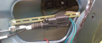
Next, we need to buy a so-called “actuator” (an electric motor (also known as a gearmotor, also known as a door activator) with a contact group, that is, it will perform not only the role of an electric motor, but also the role of a microswitch at once). I didn’t “reinvent the wheel” and install some strange actuators with strange alarms, which are not sold in all auto parts, for which you need to drill holes in the door, I just bought a standard actuator under the number: 21093-6512110-01, he already has All the wires and necessary connectors are present, there is no need to solder or drill anything:
Actuator 21093-6512110-01
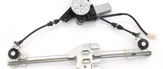
You can also install a regular 2-pin electric motor, with two wires 21093-6512210-01, which is installed in the passenger doors:
Electric motor 21093-6512210-01
But in this case, you will only be able to open the doors with the BU key; only the driver's door can be opened through the driver's lock (3 passenger doors will not open), because it does not have a built-in microswitch, like in the 21093-6512110-01 actuator, which gives a return signal on the BUBD (in fact, because of the built-in microswitch it is called an actuator, this is its main difference from a conventional electric motor).
You also need to buy a rod for the driver's door lock, I couldn't find one for sale, so I bought several repair kits for the door lock rods and several bushings for the door rods, in the end I got an almost original rod (I copied the length and bend from the rod for the front passenger's door lock), even with ability to adjust the length of the pull:
Homemade door lock rod
You also need to buy long screws to fix the actuator in the door. This is roughly what it looks like when assembled:
Door with actuator
Well, everything works, but in this state the car will close all doors only with the BU key, the actuator will strongly resist, if you open the driver's door with a regular key, it will open the door, but will immediately close it, because the CU will give the command to close the doors . This way the door can be opened a couple of times without any problems, in case of emergency.
And here we could finish the article... But then I thought about it and decided that I want to keep both the functionality of the control unit and, just in case, keep the standard functionality of the central lock (so that all doors can be opened with a key).
Without soldering, I added the 3-pin block so that I could interrupt the constant negative (black wire):
Rework
Now in one position of the switch, only the control unit works, in another position of the switch, only the central lock works, while nothing is bridged and everything works. I placed the switch together with the window lift buttons into the “stuff pocket” of the door.
I placed and connected a light bulb, which, attention, blinks. This LED is connected to a separate small red connector on the control unit; it blinks when the control unit is in the “closed” state.
Bulb
Bottom line
In this simple way, we installed the Chinese central locking control unit without cutting a single factory wire or drilling a single extra hole in the body.
PS - in 3 months of operation nothing burned, melted or exploded. The control unit does not discharge the battery, since it is not an alarm and it does not have a constant connection with the key fob; the only source of consumption is the light bulb. The BU key is triggered when it is relatively close to the car; the CU's antenna is not large and picks up the signal in different places at a distance of 5 to 20 meters.
Price: - BU: 900 rubles - Actuator: 390 rubles - Door rod repair kit: 108 rubles (2 sets) - Door rod bushing: 40 rubles (2 pcs.)
What is required to install central locking on 2 doors?
- A working and installed car alarm system with power outputs for controlling door locks.
- Activators, actuators, actuators, solenoids, electric drives or, finally, just central locks - 2 pcs.
- The wires are two-core, copper. The diameter or cross-section of each wire must be at least 0.75 square. Length about 3-4 meters.
- Plastic clamps - 10 pieces, maybe more, “in reserve.”
- Other: electrical tape, heat shrink tubing, wire cutters, screwdriver, soldering iron, solder, multimeter, drill, drill bits, electrical extension cord, etc.
Before we begin directly installing central locks, we will analyze each point above in order, in more detail.
1) In this article we will not talk about how to install an alarm yourself, but we will assume that it is already installed. The cheapest option (about 1,300 rubles) is a simple alarm without feedback.
Which model to choose, how to connect correctly, how much it costs and other questions about car alarms will be discussed in another article. Just a few important points to keep in mind.
Firstly, the main alarm unit must have a connector (usually 6-pin) with power outputs for connecting door locks. Secondly, before purchasing, decide in advance whether you need an additional alarm channel. It can be used to open the trunk or, for example, implement the “light path” function and other similar functions. It all depends on your imagination and ideas, so it’s up to you. 2)
Lock activators are not called by any name, so don’t be surprised by so many names. We will stick to this term. The central locking solenoid most likely refers to an electromagnet, which is most often installed to open the trunk. In terms of power (traction force) it is much stronger than plastic activators, but it is also more expensive.
The approximate price for a regular central locking activator with 2 outputs (two-wire electric lock) is 100-120 rubles. a piece. For 2 doors you will need two activators, the total cost is about 250 rubles. The kit for each activator includes a special strip for attaching the central lock and self-tapping screws, as well as a rod, screws and a metal retaining plate.
3) To save insulating tape, copper wires in general insulation around the insulated conductors, but you can also buy them separately (single-core). The cross-section of the conductor must be at least 0.75 square. The current consumption of a conventional electric central locking drive can reach 5A at its peak.
In auto stores you can choose wires of various diameters, colors and lengths. Some are sold in ready-made installation kits or kits. Individually or “by meter,” most often, single (single) wires are found.
We recommend going to a regular electrical supply store and purchasing a two-conductor copper cable (the individual wire of which has a stranded conductor). For example, a PVS 2×0.75 cable (with a polyvinyl chloride sheath) or a PVS 2×1 mm cable is suitable. These wires are used to connect various electrical appliances, power tools and other machines and devices. The cost is about 12-15 rubles per 1 meter.
You can look for special automotive PGVA wires, which are intended for automotive equipment and instruments. They also have polyvinyl chloride insulation and are undoubtedly suitable for connecting central locks.
For reference: PGVA wires are designed for flexible connection of electrical equipment and devices with a low rated voltage (up to 48 V) in temperate, tropical and cold climates. PGVA wire is resistant to vibration loads, cracking, gasoline and oils. When laid alone, it does not spread fire.
When installing additional devices and using a second alarm channel, carefully study the table with permissible current loads. Most likely, to install a powerful solenoid that will open the trunk lock, an additional unloading relay will be required.
Plastic tape clamps will be needed to secure the wires. Purchase at will, 10 pieces will be enough.
A set of 100 pieces measuring 2.5×100 costs about 50 rubles.
5) Other tools, devices and materials that may be needed during installation.
Design and malfunctions of the central locking VAZ 2114
A useful addition to the design of any vehicle is a central lock, which simultaneously with opening the driver's door allows you to control all the doors of the car. Unfortunately, the VAZ-2114 central lock sometimes starts
does not function correctly, this is manifested in the lack of response when turning the key in the lock or when pressing the control key on the remote control. Let's consider the main reasons causing the malfunction of this unit.
Useful video
You can glean additional useful information from the video below:
Published July 05, 2019
This review discusses how to connect an alarm system to the central locking of the following cars: VAZ-21099, as well as 2110 and 2115. There are three standard connection schemes: for central locking controlled by negative polarity, positive and variable. But different cars have their own nuances. Sometimes it is necessary to add a fuse to the “+12 Volt” wire, sometimes, on the contrary, this is not required. VAZ locks, in turn, belong to the simplest type, the first. But the standard scheme published on the Internet is not suitable for them.
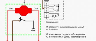
How does the VAZ-2114 central lock function and where is it located?
This unit is aggregated with a lock on the driver's door through a control element (electric drive), which, in addition to allowing you to open or close it, additionally generates signals sent to the VAZ-2114 central locking unit, where, after their analysis and processing, commands are generated for actuators of the remaining doors of the car.
When closing, the control unit rod closes the corresponding pairs of contacts, as a result of which voltage is supplied to the other drive modules, which drives them. When opening and closing, different contact pairs are closed.
The figure shows a simple diagram of the VAZ-2114 central locking:
Conclusions, purchasing a central locking system with remote control and other useful information
In order to install a central lock that will close all doors when turning the key, you should purchase a separate central locking unit (small “black box”), as well as a special master activator (5 pins) for the driver’s door, or also for the front passenger door (where there is a lock cylinder and the ability to open the door with a key).
In this case, there is no need to install an alarm, and the process of installing and connecting the actuators is similar to the example above. The only differences are that you will have to lay additional wires for the driver’s door electric lock, and also “figure out” the connection diagram for the central locking control unit.
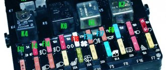
Common node faults
Often the central locking of the VAZ-2114 is controlled incorrectly due to the fact that the contact pairs are closed with a delay. A common reason for this is a violation of the adjustment of the thrust located between the gearmotor and the lock button, or its jamming. Simply put, when the button is pressed, the position of the rod does not allow the contact pairs of the drive to be completely closed.
The door on the driver's side may be locked, while the others will remain open due to the fact that the contacts of the control unit are not fully closed. This malfunction is purely mechanical in nature, and to eliminate it, it is enough to adjust the rod or the free play of the button in case it gets stuck.
In addition, such a problem can be caused by a malfunction of the VAZ-2114 central locking relay. In this case, you will have to replace the failed element.
In the case when the VAZ-2114 central locking completely stops responding to commands given by the driver, it is worth moving on to checking the electrical part of this unit. It is possible that this behavior of the system is caused by a blown fuse. Note that it can fail not only in the event of a short circuit, but also from constant overloads caused by the heavy movement of the core, or a violation of the adjustment of the rods.
Quite often, the reason why the VAZ-2114 central lock does not work is a violation of the integrity of the electrical wiring supplying power to it. The wires in the driver's door of a vehicle almost always break because it opens and closes more often than others. You can determine the damaged section of the wire using a multimeter. Less often than not, the control unit fails. In this case, the entire system either completely stops working or performs its functions incorrectly.
To prevent module malfunctions, it is necessary to pay attention to the condition of the activator, since its contacts can oxidize or burn, causing malfunctions. Periodic cleaning will significantly extend the life of the module.
Settings
After the alarm system on the VAZ 2114 is fully connected, its final configuration should be performed.
It is carried out as follows:
- Disable security.
- Set the ignition key in the lock to o.
- Press the button labeled Valet 6 times in a row.
- After the step marked “3”, immediately turn on the ignition (6 beeps should sound).
- Using the Valet button, select the required function (their list is given in the table below). To set it to the required value, press the corresponding key on the alarm key fob.
In this case, the most optimal (recommended) settings will be the following:
- for function 12 - value 3;
- for function 11 - value 4;
- for function 9 - value 3.
You can check whether the alarm is connected and configured correctly as follows:
- Disconnect the yellow cord coming out of block A91 from terminal 15 of the ignition switch.
- Turn the ignition key and start the engine.
- Pay attention to the alarm LED - if connected correctly, it should blink continuously.
The last thing I would like to talk about today is the importance of correctly connecting the tachometer, which directly affects the operation of the autostart.
To avoid errors, it is recommended to make this connection strictly in the following order:
- connect the red wire from the BUBD connector to the positive 12 volt terminal;
- connect the black wire of the 18-pin connector to the vehicle ground;
- Connect the gray-black wire of the same connector to the wire coming from the tachometer.
If you then turn on the ignition, then if the tachometer is connected correctly, the alarm indicator will begin to blink evenly.
How the central lock works
The central locking algorithm consists of sending an impulse to the VAZ 2114 central locking control unit, which analyzes the received signal and generates commands that control the door locks. They are either opened or locked.
General scheme of central locking
Elements that activate the central locking are connected to pin 30. If contact 87 closes, then the activator outputs will be affected by ground. When a certain relay 30 is activated, the contact will connect to the positive. Thus, the activator will receive power and the rod will begin to move. The control unit rod closes different pairs of signals depending on what action needs to be performed: closing or opening the doors.
Since the central locking activators are connected in parallel, all doors will either open or lock at the same time. Central locking can be pneumatic or electric. The first type of device includes a control panel, compressor and tubes. In an electric one, the main element is a motor, thanks to which the mechanisms are activated.
Replacing the driver's door lock mechanism, connecting the central locking via 5 pins. starline activator
Good day to all! It was possible to eliminate the problem with the tight opening (jamming) of the outer door handle through many ways and tests, namely: At first, adjusting the pull on the outer door handle did not help. Then I decided to change the lock mechanism - I took the lock from the store, it turned out to be of poor quality and after installation it was all loose and began to jam worse than the old one, I had to remove it and install the old one temporarily and at the same time remove the outer handle of the driver's door (the old model) and wash the moving elements with carburetor cleaner to prevent the trigger from sticking in the open position, there was a lot of dirt