- The principle of operation and design of a turbocharger
- Cooling system and turbocharging device
- Oil cooling
- Integrated cooling with oil and antifreeze
- Design features
- Improved turbocharging
- Innovative developments
- Conclusion
The turbine of a car is designed to increase the fuel pressure in the intake manifold to ensure maximum oxygen flow into the chamber where combustion occurs. The main purpose of the turbine is to significantly increase engine power. Even an increase in pressure by 1 atmosphere in the manifold leads to a double portion of oxygen entering the engine. This allows even a small engine to produce as much power as its non-turbocharged counterpart, which is twice the size.
Turbine appearance
The principle of operation and design of a turbocharger
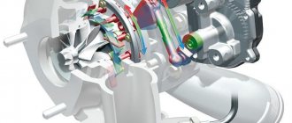
Let's look at how a turbine works in a car. The exhaust gas flow flows from the exhaust manifold into the hot part of the turbine, where it acts on the impeller blades, causing it to move along with the shaft. The impeller of the compressor located in the cold compartment of the turbine is also attached to it. When rotating, it increases the pressure in the intake system, providing an increased flow of fuel and air into the combustion chamber.
Turbine operation diagram
The design of a car turbine is not complicated, it consists of:
- Compressor volutes, which suck in air and then pump it into the intake manifold;
- Snail located in the hot part - here the exhaust gases are forced to rotate the turbine, after which they are released into the exhaust gas system at the outlet;
- Compressor impellers, as well as its counterpart in the hot part;
- Ball bearing cartridge;
- A housing connecting the volutes, having a cooling system and bearing systems.
General turbine design
During operation, the device is subjected to significant thermodynamic loads. The exhaust gases entering the turbine reach a temperature of 900°C, which is why its body is made of cast iron, and a special technology is used for casting. Turbine shaft speeds can reach 200,000 rpm, so high-precision parts are installed into the design, which are carefully adjusted and then balanced. The turbine also places high demands on lubricants. The individual turbochargers are equipped so that the lubrication system also cools the bearing assembly.
What is a turbo pit?
It is worth adding that the turbocharger impeller is capable of developing up to two hundred thousand revolutions per minute, due to which this device is characterized by great inertia or, in other words, has a “turbo pit”, which manifests itself when the gas pedal is sharply pressed. At this moment, the impeller is slowly set in motion, and you have to wait for some time for the car to begin to pick up speed.
This effect lasts only a few seconds, but nevertheless, it does not provide much pleasure when accelerating the car. To date, manufacturers, one way or another, have been able to eliminate the “turbo lag” effect by installing two bypass valves. One is intended for exhaust gases, the task of the second is to bypass excess air into the turbocharger pipeline from the intake manifold.
Thanks to this system, the speed of the impeller when releasing gas decreases at a slow pace, while when you sharply press the accelerator pedal, the air mass enters the engine in full.
Oil cooling
Advantages:
- Simple design;
- Cheaper turbocharger.
Flaws:
- Less efficient compared to a system that uses antifreeze with oil; High demands on oil composition;
- The need to change it frequently;
- Demanding temperature control.
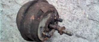
Oil cooled turbine
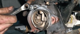
Initially, the turbocharger device had only oil cooling, which quickly reached high temperatures passing through the bearings. Such oil begins to boil immediately, a coking effect occurs, due to which the channels become clogged, significantly limiting the access of cooling and lubrication to the bearings.
As a result, the bearings wear out, become jammed, and require expensive repairs. There are several reasons for this problem:
- Poor quality oil or not the one recommended for the engine;
- Exceeding the oil change period;
- Malfunctions of the car engine lubrication system.
Turbine design
Publication date: 2015-04-10
Content
- Compressor
- Compressor characteristics
- Surge area
- Saturation line
- Limit speed
- Turbine
- Performance characteristics
- Turbine materials
- Double Entry Turbines
- Response
- Ceramic turbine wheels
- Water-cooled enclosures
- Control system
- Bypass control on turbine side
- Variable geometry turbines
- Bearing assembly
- Support bearings
- Thrust bearing
- Oil drain
- Seals
- Thermal load on bearings
- Heat shield and oil spray cooling
- Thermal decoupling
- Water cooling
- Recirculation valve
The design and basic functions of a turbocharger (TC) have not undergone fundamental changes since its invention by the Swiss engineer Alfred Büchi, who proposed the idea of turbocharging in 1905. A turbocharger, as its name suggests, consists of a turbine and a compressor connected by a common shaft. The turbine, driven by exhaust gases (EG), transfers rotational energy to the compressor.
In automotive engineering, the most popular are centrifugal compressors and radial-axial (centripetal) turbines, which are the basis of most modern fuel compressors.
Compressor
Part of the turbocharger, the centrifugal compressor consists of three main components: the compressor wheel, the diffuser and the housing. By the rotating wheel, the air flow is sucked in in the axial direction, accelerated to high speed and then forced out in the radial direction. The diffuser slows down the high-velocity air flow with virtually no loss, so that both its pressure and temperature increase. The diffuser is formed by the compressor support disk and part of the spiral casing (volute). The latter, in turn, collects the effluent flow and slows it down even more before exiting the compressor.
The main components of a compressor are the impeller (compressor wheel), diffuser and scroll casing. The diffuser is a narrow channel formed by the compressor support disk and part of the housing.
Compressor characteristics
Compressor performance is determined by a duty map that reflects the relationship between pressure ratio and volume or mass flow. For ease of comparison, the volumetric and mass flow rates of the compressor are related to standard conditions at the compressor inlet. The working area of the map for centrifugal compressors is limited by zones of unstable modes (on the left – the surge line, on the right – the saturation line), as well as the maximum permissible rotation speed. A compressor for automotive applications must operate stably when air flow varies over a wide range. Therefore, it must have a mode map with a wide working area.
Surge area
An automobile turbocharger is a unit consisting of a centrifugal compressor and a radial-axial turbine connected by a common shaft.
The mode map on the left is limited by the surge line. In essence, surging is a disruption of the air flow at the inlet of the compressor. If the volume flow is too low and the pressure ratio is too high, the flow is separated from the inlet planes of the blades and the normal pumping process is disrupted. The air flow through the compressor is reversed until the pressure drop stabilizes. The flow direction returns to normal, the boost pressure is restored and the cycle repeats. This flow instability continues at a fixed frequency. The resulting acoustic noise is known as surging.
The surge line is shifted to an area of lower volumetric flow rates by using blades with backward-curved edges, so that the operating range of compressor flow rates increases. The reverse bending of the blades results in the formation of long, gradually widening channels. They slow the flow rate and produce less boundary separation than radial-edge blades.
The "snail" collects the high-speed flow and slows it down, which leads to an increase in temperature and pressure.
The diffuser width also has a positive effect on the location of the surge line. In general, compressors with narrow diffuser configurations have a more stable mode map.
Saturation line
The maximum volume flow of a centrifugal compressor is usually limited by the inlet cross-section. When the flow velocity at the wheel inlet reaches the speed of sound, further increase in flow becomes impossible. The saturation line can be determined by the steeply decreasing curves of the maximum compressor speed on the right side of the regime map. The compressor inlet cross-section can be increased, and the saturation line shifted to the area of high flow rates, by shifting the leading edge of every second blade (so-called splitter blades).
When the compressor inlet diameter increases, the so-called hub ratio increases -
the
ratio between the inlet diameter and the wheel diameter. This leads to an increase in maximum flow. Due to requirements for the strength of parts and for aerodynamic reasons, an increase in the hub ratio is possible to approximately 0.8. For the same reason, such large hub ratios only allow for the relatively low pressure ratios required in passenger cars.
Thinning the blades and reducing their number increases the cross-sectional area at the entrance to the wheel, so that the saturation line moves towards higher volumetric air flow rates. The minimum thickness of the blades is limited by casting technology and strength requirements. However, when the number of blades is reduced, the degree of pressure increase also decreases.
Thus, the compressor wheels of passenger car turbochargers are characterized by a high hub ratio and a reduced number of thin blades with a strong reverse bend.
The compressor is the “cold” part of the engine, the function of which is to increase the pressure, and, at the same time, the density of the air entering the engine.
Compressor housings for commercial diesel engines, where both a high pressure ratio and a wide range of operating conditions are required, are often manufactured with recirculation channels. Through the channels, part of the intake air is returned from the compressor to the main flow at its inlet. Thanks to the recirculation that occurs, the flow stabilizes and the surge line shifts towards lower volumetric flow rates. Moreover, in the same way, air can be supplied to the wheel in the area behind the limiting inlet section, so that the saturation line shifts to the region of high flow rates.
Limit speed
The rotation speed of the compressor wheel is limited by the loads experienced by its components. The maximum rotational speed is determined by the permissible blade tip speed and the outer diameter of the wheel. The permissible blade tip speed is usually about 520 m/s. If no measures are taken to reduce loads, increasing speed results in shorter service life.
Turbine
The turbocharger turbine (TC) consists of a turbine wheel and a housing. It converts exhaust gas (EG) energy into mechanical energy to drive the compressor. The exhaust gas stream carries energy in the form of high pressure and temperature. After passing through the turbine, the energy of the gases (pressure and temperature) decreases. The difference in pressure and temperature of gases between the inlet and outlet of the turbine is converted into kinetic energy of rotation of the turbine wheel.
There are two main types of turbines: axial flow and radial flow. For wheels up to 160 mm in diameter, only radial turbines are used. The efficiency of small radial turbines is higher, and the manufacturing cost for large production volumes is significantly lower than that of axial turbines. Therefore, they are commonly used in passenger and commercial diesel engines, as well as industrial power units.
In the volute of radial (centripetal) turbines, exhaust gas pressure is converted into kinetic energy and they are directed at a constant speed from the periphery to the turbine wheel. The transformation of kinetic energy into shaft power occurs in the turbine wheel. It is designed so that almost all the kinetic energy of the gas is converted by the time it leaves the impeller.
Performance characteristics
Compressor impeller structure.
Splitter blades increase the inlet cross-section of the compressor. Reverse bending of the blades at the outlet of the compressor wheel is a way to combat surge. The power of a turbine increases as the pressure difference between its inlet and outlet increases, that is, when more exhaust gases (EG) accumulate in front of the turbine. This occurs as a result of an increase in engine speed or an increase in the temperature of the gases due to their greater energy.
The behavior of the turbine characteristic is determined by the relative cross-section of the flow path. The smaller the relative cross-section, the more gases accumulate at the turbine inlet (the pressure in front of the turbine increases). As a result of increasing pressure drop, turbine performance increases. Thus, with a decrease in the relative cross-section, the boost pressure increases.
The relative cross section of the turbine can be easily varied by replacing its casing. Most manufacturers of turbochargers (TC) offer casings of different sizes for each type of turbine. This makes it possible to vary the boost pressure within a wide range by selecting the required relative cross-section of the flow part of the turbine housing.
In addition to the relative cross-section, the mass flow of gases through the turbine is also influenced by the area of the hole at the outlet of the wheel. Mechanical processing of a cast turbine wheel along the contour - trim - makes it possible to regulate the cross-sectional area and, consequently, the boost pressure. Increasing the wheel contour results in a larger flow area. Within the same TK series, manufacturers offer turbine wheels with different trims, which are made from the same injection moldings.
In variable geometry turbines, the flow area between the volute channel and the wheel outlet varies. At the entrance to the turbine wheel, it is changed using movable controlled blades or a sliding ring that partially covers the section.
In practice, the performance characteristics of the TK turbine are described by maps showing the dependence of the exhaust gas flow parameters on the pressure drop across the turbine. The turbine map shows the turbine mass flow and efficiency curves for different rotational speeds. To simplify the maps, the dependence of flow rate and efficiency can be presented in the form of averaged curves.
Turbine materials
Since the turbine is exposed to very high temperatures during engine operation and after it is stopped, the turbine wheel and housing are made of materials with high heat resistance. In general, turbine impellers are made from nickel-based alloys such as Inconel 713 and GMR 235. The main components of these alloys are nickel and chromium. While GMR 235 operates at turbine inlet temperatures of up to 850°C, Inconel 713 (73% nickel, 13% chromium) is used at temperatures above 1000°C.
The choice of material for the turbine casing also depends on the temperature. Today, gray cast iron GGG40 with spherical graphite (up to 680°C) is used less frequently. For most diesel units, silicon-molybdenum cast iron GGG SiMo 5.1 (up to 760°C) or GGV SiMo 4.5 0.6 (up to 850°C) is used. Less commonly, for exhaust temperatures up to 850 °C, high-alloy nickel-chromium cast iron GGG NiCrSi 20 2 2 (Niresist D2) is used.
Most turbochargers for gasoline engines with exhaust temperatures up to 970°C use the alloy GGG NiCrSi 35 5 2 (Niresist D5). For the highest temperatures up to 1050 °C, which will be required in gasoline engines of the near future, heat-resistant cast austenitic steel is used.
Double Entry Turbines
The pressure of the exhaust gases (EG) flowing out of the engine is not constant - it pulsates in accordance with the alternation of exhaust strokes in different cylinders. Pulse charging systems use exhaust gas pressure pulsations to briefly increase the pressure drop across the turbine. Due to the increase in pressure drop, the efficiency of the turbine increases, improving its operation until a large, efficient flow of gases flows through it. As a result of more complete utilization of exhaust gas energy, the charge pressure characteristics and therefore the behavior of the torque curve are improved, especially at low engine speeds.
To prevent mutual influence of the cylinders at different intake-exhaust strokes, they are divided into two independent groups. Each group is combined into its own exhaust manifold, which transmits exhaust gas directly to the turbine inlet. In this case, a dual-inlet turbine allows the exhaust gas from the two groups of cylinders to be recovered separately. Passenger car engines often use undivided manifolds and "single-scroll" casing turbines. This allows you to make the manifold more compact and position the turbine closer to the cylinder head. Since the cross-section and length of the gas supply channels are smaller here, the advantages of pulse charging are leveled out.
And yet, in some cases, dual-entry turbines are used in gasoline engines of passenger cars. Their advantage is good torque characteristics at low exhaust pressure. At the same time, they also have disadvantages - the high thermal load of the dividing partition and the expensive production of small housings with an integrated bypass, especially if the material must be cast steel due to high temperatures.
Response
For passenger car engines, the inertial characteristics of the turbocharger (TC) play a vital role. Slow response to changes in the position of the accelerator pedal, also called “turbo lag,” is often perceived as a factor that reduces vehicle handling. In recent years, this negative effect has been compensated by the use of smaller TCs. They have a smaller cross-section of the flow path and lower rotor inertia as a result of the use of wheels of smaller diameter. Thus, as the rotation speed of the turbocharger increases, it is necessary to spin up a rotor of less mass. The moment of inertia of the turbine wheel can also be reduced by removing the support disk segments between the blades. To an even greater extent, the dynamic characteristics of the fuel pump can be improved by using turbines with variable flow path geometry.
Optimal flow conditions and low heat loss are achieved in integrated charging systems with integrally molded exhaust manifold and turbine housing, resulting in improved response characteristics. Other arguments for the use of such systems are a reduction in weight of up to 1 kg, as well as an increase in the free space between the engine and the passenger cabin, which is often vital for safety reasons.
Ceramic turbine wheels
Compared to metal wheels, ceramic turbine wheels are significantly lighter, which improves the response characteristics (sensitivity) of the turbocharger. Modern ceramic materials have made it possible to develop such wheels suitable for mass production. However, ceramic materials are very fragile and can be easily destroyed by foreign particles. Moreover, the blades of such turbines are thicker and therefore less efficient, so they are rarely used in automotive applications.
Titanium aluminide has the same density as ceramic. This material is comparatively less susceptible to destruction, and the blades are as thin as metal. Its disadvantage is low temperature resistance (maximum 700°C).
Typical compressor mode map. The working area of the mode map is limited by the surge, saturation and maximum permissible rotation speed lines.
Water-cooled enclosures
When developing turbochargers (TC), safety aspects must also be taken into account. For example, hot surfaces should be avoided in marine engine compartments due to the risk of fire. Therefore, TK turbine housings for marine applications are manufactured with water cooling or coated with insulating materials.
Control system
The traction characteristics of modern turbo engines must meet the same high requirements as the characteristics of naturally aspirated engines with identical power parameters. This means that full boost pressure must be available starting from the lowest possible engine speeds. This in turn can only be achieved by controlling the turbocharger on the turbine side.
Bypass control on turbine side
Installing a bypass valve in the turbine part of a turbocharger (TC) is the easiest way to control the boost pressure. The geometric parameters of the turbine are chosen in such a way as to provide the torque characteristic at low speeds necessary to achieve the specified dynamic performance of the vehicle. With this design of the fuel pump, shortly before reaching the maximum torque, an excess amount of exhaust gases begins to flow into the turbine. Thus, as soon as the nominal boost pressure is reached, excess exhaust gases are directed through the bypass channel, bypassing the turbine wheel. The wastegate valve, which opens and closes the bypass, is typically actuated by an air chamber with a spring-loaded diaphragm that responds to boost pressure. So, as the engine speed further increases, the boost pressure remains at a constant level.
In this very economical solution, the control chamber diaphragm, preloaded by a coil spring, is subjected to boost pressure. As soon as the boost pressure overcomes the pre-compression force of the spring, the rod opens the bypass valve plate through a lever and the exhaust gases begin to flow around the turbine into the exhaust system.
Electronically controlled charge pressure control systems are increasingly being used in modern gasoline and diesel engines. Compared to purely pneumatic control, which only acts as a pressure limiter at full load, flexible control allows the optimum boost pressure to be set at part load. Electronic control works in accordance with various parameters, such as charge air temperature, fuel quality and injection (ignition) timing parameters. It also becomes possible to briefly “overboost” during intense acceleration.
The mechanical drive of the bypass damper operates in the same way as in the case described above. Instead of full boost pressure, modulated control pressure is applied to the control chamber diaphragm. It is less than the total boost pressure and is produced by the so-called proportional valve. This ensures that the diaphragm is exposed to a combination of boost pressure and compressor outlet pressure in varying proportions. The proportional valve is controlled by the engine electronics and operates at a frequency of 10 to 15 Hz. Compared to a conventional control system, the spring pre-compression force is significantly lower, which allows control also in partial load modes, that is, at lower boost pressure.
In electronic control systems for turbochargers of diesel engines, the pneumatic chambers are regulated by vacuum.
Variable geometry turbines
Bypass control systems control turbine power by directing part of the exhaust gases (EG) bypassing it. Thus, the “free” energy of gases is not fully used. Turbines with variable geometry make it possible to vary the cross-section of the turbine flow path depending on the operating mode of the engine. This makes it possible to completely utilize the exhaust gas energy by optimizing the configuration of the channel through which the exhaust gases enter the turbine wheel for a given engine mode. As a result, the efficiency of the turbocharger (TC) and, accordingly, the engine is higher than what can be achieved with bypass regulation.
Today, turbines with RSA in the form of moving guide vanes (VNT, VTG, VGT) are the most advanced solution for modern passenger diesel cars. As a result of continuous adaptation of the turbine channel flow area to the engine operating conditions, fuel consumption and harmful emissions are reduced. High torque already at low speeds and an adequate control strategy ensure a significant improvement in dynamic performance.
The movable guide vanes between the volute housing and the turbine wheel influence the pressure recovery process and thus the turbine output characteristics. This allows the gas flow through the turbine to be varied in a range of 1:3 at good efficiency levels. At low speeds, the cross-section of the turbine flow path is reduced by closing the guide vanes. The boost pressure and therefore the engine torque increases as a result of an increase in the pressure difference between the inlet and outlet of the turbine. As engine speed increases, the control vanes gradually open. The required boost pressure is achieved with a low pressure drop across the turbine, thereby reducing fuel consumption. When accelerating the machine from low speed (engine speed), the controlled blades close to obtain maximum energy from the exhaust gas. As speed increases, the blades open and adapt to the corresponding operating conditions.
Currently, blade control is predominantly electronic, using a vacuum-controlled control chamber and a proportional valve. In the future, electric drives with positive feedback will increasingly be used, allowing precise and extremely flexible control of boost pressure.
The exhaust temperature of modern high-efficiency diesel engines can reach 830°C. The precise and reliable operation of control blades in a flow of hot gases places high demands on materials and precision tolerances in turbine design. Regardless of the size of the turbocharger, the guide vanes must have minimum clearances to ensure reliable operation throughout the life of the vehicle. As the size of the TC decreases, the relative flow losses through the turbine increase and its efficiency decreases. Therefore, the goal of many developments is to push these limitations on the scope of application of VTG technology as far as possible towards small-sized TCs.
An alternative solution is turbines with a regulating mechanism in the form of a movable (sliding) ring (VST-variable sliding turbine). Simplicity of design and performance of many functions by a small number of components are advantages for small turbines or where operation at high exhaust temperatures is required. This is especially applicable in compact diesel engines with a displacement of less than 1.4 liters. Advantages: high efficiency, low price and reduced installation dimensions. For gasoline engines with high exhaust temperatures, VST technology is a reliable option for controlling boost pressure by changing the geometry of the turbine flow path.
The robust VST mechanism withstands high exhaust temperatures significantly better than VTG with guide vanes. The bypass, which is necessary for gasoline engines even in TCs with variable geometry due to the large range of flow changes, is integrated into the control mechanism.
The turbine housing is similar to twin-scroll turbines (with a two-channel guide vane). The partition separating the channels does not extend to the inlet flange, but begins inside the cochlea. At low engine speeds, only one channel is open. The second channel, which is closed by a sliding ring, gradually opens as the speed increases. Then the sliding ring also opens the bypass channel, leading from the entrance to the turbine along the outer contour of the sliding ring to the outlet of the turbine. This further increases the gas flow through the turbine. To regulate the cross-section of the flow part and open the bypass channel, only one control mechanism is required. Both pneumatic and electronic drives can be used.
Bearing assembly
The turbocharger rotor (TC) rotates at a frequency of up to 300,000 min -1. The service life of the vehicle must correspond to the engine life, which can be 1,000,000 km for a commercial vehicle. Only sliding bearings specially designed for technical equipment can meet such stringent requirements at an acceptable cost.
Support bearings
In a plain bearing, the shaft rotates virtually without friction on an oil film inside the bearing sleeve.
Oil is supplied to the turbocharger (TC) from the engine lubrication system. The bearing assembly is designed in such a way that “floating” bronze bearing bushings are located between the stationary housing and the rotating shaft. They rotate at a frequency that is half the shaft speed. This allows high-speed bearings to adapt in such a way that at any operating modes of the TC there is no direct metal-to-metal contact between the shaft and bearings.
In addition to the lubrication function, the oil film in the bearing gaps plays the role of a damper, which helps stabilize the shaft and turbine wheel. The hydrodynamic load-bearing capacity of the film and the damping characteristics of the bearing are optimized by the size of the gaps. Thus, the lubricating film thickness for the internal clearances is selected based on the bearing load, while the thickness of the external clearances is determined based on the bearing damping. The clearances in the bearings are several hundredths of a millimeter. Increasing the clearances will lead to softer damping and, at the same time, to a decrease in the load-bearing capacity of the bearing.
The so-called cartridge is a special type of journal bearing. The shaft rotates in a stationary one-piece bushing, from the outside of which oil is pumped. The external clearance is selected solely from the condition of bearing damping, since the cartridge does not rotate. The resulting smaller bearing width makes it possible to create a more compact TC.
Thrust bearing
None of the considered types of support bearings, neither free-floating bushings nor a fixed floating cartridge, accept loads in the axial direction. Since the gases act on the compressor and turbine wheels in the axial direction with different forces, the rotor of the turbocharger (TC) experiences an axial load. It is perceived by a thrust sliding bearing with a conical plane (working surface). Two small disks mounted on the shaft serve as contact surfaces. The thrust bearing is fixed in the central bearing housing. The oil deflector plate prevents oil from entering the shaft seal area.
Oil drain
Oil is supplied to the turbocharger (TC) at a pressure of approximately 4 bar. Since oil is drained from the turbine at lower pressure (by gravity), the diameter of the drain tube is significantly larger than the oil supply tube. The oil flow through the bearing housing should be as vertical as possible, from top to bottom. The drain pipe should extend into the crankcase above the oil level. Any obstacle to draining the oil results in an increase in back pressure in the bearing housing. In this case, oil begins to leak through the o-rings into the compressor and turbine.
Seals
The central bearing housing must be sealed against the breakthrough of hot exhaust gases from the turbine into it and against oil leaks from the housing. To do this, split rings similar to piston rings are installed in the grooves on the rotor shaft, on the compressor and turbine sides. The rings do not rotate, but are motionlessly wedged in the central body. This is a non-contact seal, a type of labyrinth seal. Thanks to numerous sudden changes in the direction of flow, it makes it difficult for oil to leak and allows only a small amount of exhaust gases to enter the crankcase.
Thermal load on bearings
Given the short distance between the center housing and the hot turbine housing, heat can penetrate into the center housing and heat the oil to the coking temperature. Oil coke could then settle in gaps and on surfaces, clog oil passages and impair the performance of bearings and seals. Large amounts of hydrocarbon deposits can cause lubrication deficiency and boundary friction, leading to accelerated wear of the bearing system.
Heat shield and oil spray cooling
A heat shield located behind the turbine wheel support plate prevents hot exhaust gases from coming into contact with the central housing. In some designs, when the engine is running, oil is sprayed onto the rotor shaft through a small spray hole in the bearing support on the turbine side, cooling the shaft and reducing the risk of coking.
The highest temperatures in the central housing are reached shortly after the engine is stopped. The hot turbine housing heats up the bearing system, which is no longer cooled by engine oil.
Thermal decoupling
By thermally decoupling the right bearing arrangement, heat transfer from the turbine housing to the bearing system is reduced even after the engine has been stopped. To do this, the bearing system is located below the oil supply point, just as the power unit is located under the wing of an airplane. The right bearing support is no longer in contact with the hot wall of the central housing, meaning heat transfer to the bearing system is limited.
Water cooling
Gasoline engines, whose exhaust gas temperatures are 200-300°C higher than diesel engines, are usually equipped with turbochargers with cooled central casings. When the engine is running, the central housing is integrated into its cooling circuit. After turning off the engine, residual heat is removed through a small circulation ring, which is activated by an electric pump with a thermostat.
Recirculation valve
In gasoline turbo engines, the throttle valve, which controls engine load, is located after the compressor, in the intake manifold. At the moment of sudden release of gas, the damper closes, and the compressor, due to its inertia, continues to pump air into an almost closed volume. As a result, the compressor would begin to surge. The rotation speed of the turbocharger (TC) would quickly drop.
Starting at a certain pressure, a spring-loaded valve opens and directs air back into the compressor inlet, limiting pressure rise and eliminating surge. The engine speed remains high and boost pressure will appear as soon as the accelerator is applied.
Integrated cooling with oil and antifreeze
The advantage of this option is the greater efficiency of the resulting cooling. A significant drawback is the complexity of the design of turbochargers, which increases their cost.
Turbine with oil and water cooling
The turbocharging device in the version of cooling turbines with antifreeze and oil is more complex, since it has a separate oil circuit, as well as a system with coolant. But the work efficiency increases and the problems of oil boiling are eliminated.
For such a turbocharger, oil serves, as before, to cool and lubricate the bearings, and antifreeze supplied from the general engine cooling circuit prevents overheating and prevents the oil from boiling. This complexity increases the price of the turbocharger.
Flaws
Why is this element not present on all internal combustion engines? First of all, the use of a turbine increases the cost of car production. In addition to the snail itself, a number of other elements are required.
In addition, to work with the turbine, the engine needs another, stronger piston system and block. This also entails additional costs. Also among the disadvantages is the so-called turbo lag (when the engine cannot gain speed in the required time). The reason for this phenomenon is the inertia of the compressor.
Design features
When a hot turbine operates, the air pumped into its casing by the compressor is strongly compressed, causing it to heat up. This causes undesirable effects because at high temperatures there is less oxygen in the air. This means that the efficiency of the boost is also reduced. To combat this phenomenon, using the recommendations of scientists, they began to install an intercooler - an auxiliary air cooler - in the turbine.
Turbine intercooler
The designers of the device note that heating the air is far from the only problem that they have to solve when designing a turbine. An urgent problem also becomes its inertia - a delay in the engine’s response to the opening of the throttle valve in the manifold.
The turbine is most efficient when a certain crankshaft speed is reached. There is even a widespread belief among car enthusiasts that turbocharging is turned on only when the vehicle speed reaches a certain value. Although the turbine operates constantly, the value of the speed at which its operation is most effective is individual for each engine.
Air blower diagnostics
How to determine without special instruments that the turbocharger is broken? Firstly, this is evidenced by a drop in engine power. At the same time, dense white smoke pours out of the muffler, and lubricant consumption often increases to several liters per 100 km. This means that the supercharger must be immediately repaired or purchased a new one - sometimes replacing worn bearings and an o-ring does not give a positive result.
Secondly, situations often arise when there is no white smoke “screen” as such. It’s just that the engine can’t reach its required power, and no warning light on the instrument panel lights up. Owners of turbocharged cars have only one solution - an urgent visit to a car service center. It’s easier for owners of turbodiesels: a problem with the air blower is eloquently evidenced by black smoke at idle. Moreover, it is far from a fact that the turbo system has hopelessly failed - it may simply be worn out and completely repairable.
| Tweet |
Improved turbocharging
Solving the problems of turbine design, the designers developed a circuit in which the superchargers of two compressors were connected. This design is called twin-turbo.
Twin-turbo turbine design
In such a system, a pair of identical turbines are used in parallel. Their task is to increase the pressure and volume of incoming air. The control system turns on the twin-turbo at the moment when it is necessary to obtain maximum power at increased speeds.
A similar compressor is implemented in the famous Japanese car of the Nissan brand, which was named Skyline Gt-R.
Nissan engine with twin-turbo system
It has an rb26-dett motor. A similar system, however, equipped with the same small turbines allows you to get a noticeable increase in power even at low speeds, while maintaining turbocharging constantly.
The series connection of different turbines is called Bi-turbo.
Bi-turbo turbine design
The design is designed in such a way that at low speeds only a small turbine operates, which provides “responsiveness” at a smoothly variable speed. If the speed increases sharply, the “large” turbine turns on.” This allows the machine to receive a significant increase in performance, and in any range of engine operation. A similar system is implemented in BMW biturbo models, the tuning of which is admirable.
Bi-turbo system from BMW
Where is it used?
Basically, such a unit can be found on modern cars. But this supercharger is not used on all internal combustion engines. A limiting factor in the use of turbines on gasoline engines is the high degree of detonation. It is associated with an increase in the rotation speed of the internal combustion engine and the enormous temperature of the exhaust gases (up to a thousand degrees). Because of this, a diesel engine turbine is often used. The operating principle of such an internal combustion engine is somewhat different. There is a lower risk of detonation, and the temperature of the gases does not exceed 600 degrees. Compressors are especially common in commercial vehicles. It is impossible to imagine a modern bus or long-haul tractor not equipped with such a turbine. If we talk about brands, the turbine is installed on the following cars:
- "Volkswagen".
- "Mercedes".
- "Volvo".
- "Mazda".
- "Audi".
- Renault.
- "Toyota".
There are other areas where a similar element is used. For example, these are power plants and internal combustion engines of ships. But here a steam turbine is already used, the operating principle of which we will consider a little later.
Innovative developments
Among the modern developments that are already delighting car owners is the VGT turbine, in which the impeller blades change their angle of inclination, directing it in the direction where the exhaust gases are directed.
Turbine with variable blade angle
When the engine speed is low, the flow area of the exhaust gases entering the turbine becomes narrower, so the “exhaust” is faster. This system is most often used for diesel units, but there are developments for gasoline engines as well.
Also among the innovative developments is the Twin-scroll system, where, thanks to the double circuit through which the exhaust gases travel, it turns out that their energy rotates a common rotor with a compressor and impeller.
Twin scroll turbine design
There are two implementation options:
- Exhaust gases pass through both circuits simultaneously and the system functions as a twin-turbo.
- The second type works like a biturbo circuit - there are two circuits with different geometries. When the revs are low, the exhaust gases follow a short path that increases energy and speed due to the small diameter. If the speed increases, the exhaust gases enter a circuit with a larger diameter - while the operating pressure is maintained in the intake system and there is no restriction for the exhaust gases. The distribution is regulated by mechanical elements - valves that switch flows.
Characteristic
A turbine is an element of the engine intake system that serves to increase air pressure by using the energy of exhaust gases. Thanks to its operation, the air mass in the combustion chamber increases.
This allows you to speed up the engine strokes and increase its torque. Also note that the first turbines were mechanically driven. The operating principle of such a turbine was to convert energy from the crankshaft. The element was connected to the latter by a belt drive. But soon such units ceased to be used. Now all manufacturers use a gas turbine, the operating principle of which allows the engine efficiency to be increased by 80 percent instead of 30.
Auxiliary elements
Since the turbine is part of the intake system, its operation is impossible without the use of an air filter, throttle valve, and intercooler.
The latter is designed to cool the oxygen, which is pumped into the chamber under pressure. The colder the air in the intercooler, the better the mixture burns in the cylinders. Also, the design cannot do without connecting and oil hoses.
Lubrication system
This is an integral part of any turbine. The operating principle of the lubrication system is simple. Oil is supplied between the bearing and the compressor housing through multiple pressure passages. But don’t think that this system is needed only for lubrication. It also cools the heated parts of the compressor. On some engines, the turbine is connected to a common cooling system. Thanks to this, better cooling is achieved, but this design is much more complex and expensive to manufacture.
In order to get rid of turbo lag, manufacturers are constantly improving the design of diesel turbines. The principle of its operation remains the same, but the following points change:
- Compressor weight. The turbine is made of both lightweight and durable materials (for example, ceramics).
- Bearing design. The lower the friction losses, the higher the turbine performance. The wheel spins more easily to nominal values.