Which owner would not want to install a tachometer on a VAZ 2105? Only those who already have it. The basic configuration does not require its presence on the instrument panel. Which is very disappointing. But if a torpedo and a shield from a VAZ 2107 are installed, then it is already there. The useful operation of the device was appreciated by professionals and amateurs. Many people cannot imagine driving without such an important device.
Installation Features
As noted above, owners of the VAZ-2105 are recommended to replace the instrument panel with the one that was mounted on the 2107. If you do not want to do this, then a remote option is selected.
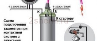
It is fixed either on the bracket supplied in the kit or in a special frame-pocket - those are sold separately. For the 2105 model, the tachometer designed for the VAZ-2106 is perfect. To connect it, you will have to cut off the connector with contacts, since there is nowhere to plug it into the “five”. Further switching is done by extending the wires and connecting them with terminal strips (sold in electrical goods stores). It is important to consider the following:
- one cable (marked with brown insulation) is attached to the plus of the ignition coil;
- black and white goes to mass;
- orange (sometimes yellow) connects to battery positive.
The electronic tachometer is installed in the same way.
Tachometer installation.
- Answer
- Go to first unread message
#21 Tumbler
- Our people
- 1294 messages
- 0 thanks
- City VAZ 21053 (Former), Moscow VAO,
- Top
- Answer
- Quote
- Insert nickname or quote
#22 andreich1137
- City: Vologda
- Car: VAZ-21074 injector
- Top
- Answer
- Quote
- Insert nickname or quote
#23 andreich1137
- City: Vologda
- Car: VAZ-21074 injector
- Top
- Answer
- Quote
- Insert nickname or quote
#24 Tumbler
- City VAZ 21053 (Former), Moscow VAO,
- Top
- Answer
- Quote
- Insert nickname or quote
#25 Victor
- City 21074, Kyiv, Ukraine
- Top
- Answer
- Quote
- Insert nickname or quote
#26 johni2004
- City VAZ 21073, Moscow,
Black - ground Red - plus when on. ignition (you can, for example, connect to the + ignition coil) Green - minus (K terminal) of the ignition coil
The remaining wires may be responsible for lighting, connecting the device as an oil pressure sensor, etc.
- Top
- Answer
- Quote
- Insert nickname or quote
#27 Victor
- City 21074, Kyiv, Ukraine
- Top
- Answer
- Quote
- Insert nickname or quote
#28 Fantom
- City VAZ 2105 88 , Peter,
gasoline level C + orange BN - white-black B backlight white S Gasoline green-red X lamp pink-red
temperature water C + orange BN - white-black B backlight white V Water sensor green-white
oil pressure C + orange BN - white-black B backlight white HN oil X lamp gray-blue
tachometer M coil B backlight white BN - white-black C + orange T damper N acc lamp brown-white P handbrake pink
Welcome to VAZ.EE+ Extended Edition
Design, principle of operation, repair and replacement of the tachometer of the VAZ 2106
Since May 2013, our portal has expanded the thematic sections of the forum for the exchange of experience: subforums have been added: Americans, Koreans, Germans, French, Japanese, due to the increase in the fleets of our visitors.
In addition to changing the style, our Chat, Mail, Entertainment and photo/video sections, Literature have become built-in and do not require separate registration. In addition, there are other useful and pleasant innovations that you can all familiarize yourself with when visiting the portal.
You can contact the administration with questions and suggestions in a special section of the forum or through the feedback form.
Important nuances
Please note that the 2105 model was produced with carburetor engines, which means you will not be able to install a tachometer designed for an injector.
If you do not understand how to connect a particular device, carefully read the instructions for it. It contains all the necessary information. And one more point - on the packaging of any tachometer the limiting number of engine cylinders is indicated. This recommendation must be followed, otherwise you will not be able to receive objective information.
Quite a lot of remote devices have a common drawback - low accuracy. For this reason, try to avoid overly cheap offers from little-known manufacturers.
Source
Why
Step-by-step connection of a tachometer on a VAZ 2109: diagram, video
The tachometer is not one of the “vital” devices of the “seven”, but its malfunction causes certain inconvenience. In addition, the situation when the VAZ 2107 tachometer jumps is a sign of problems in the ignition system or fuel supply to the engine. Therefore, at the first sign of a malfunctioning tachometer, you need to understand the causes of the breakdown and eliminate them immediately.
The connection diagram for the tachometer on a VAZ 2107 with a carburetor engine is slightly different from that used on models with an injector. But in general, the causes of the malfunction and the methods for eliminating them are similar.
Connecting a tachometer on carburetor and injection models
The connection diagram for the VAZ 2107 tachometer on an injection machine differs in that in this case the device reads data on engine speed not from the ignition coil, but from the engine ECU. In general, the connection procedure and operating principle are no different. The device has three terminals, two of which are connected to the “plus” from the ignition switch and “ground”, and to the third - a wire from the ignition coil or engine ECU.
Where to start troubleshooting
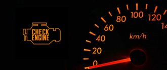
To troubleshoot, you will need a multimeter or “tester”. If the tachometer on a VAZ 2107 (injector) does not work, you should first look to see if the “Check Engine” warning light is on. If this is the case, then you can find out the cause of the breakdown by reading the error code from the controller. If the lamp does not light, you can skip this point.
Next, on the injection and carburetor models, you should check the condition of the electrical wiring going to the tachometer. The insulation of the wires must not be damaged, the tachometer must have good contact with ground, power and terminal “K” of the ignition coil or the engine ECU output. In addition, there may be a break or poor contact inside the device itself. In this case, it will have to be replaced.
If everything is in order with the wires and contacts, the problem is in the Hall sensor (on the injection “seven”), the ignition or fuel supply system.
Checking the ignition system
The VAZ 2107 tachometer circuit is the same for all models, the only difference is where it gets the data from. In the carburetor “seven”, information about engine speed is read from the ignition coil: every two spark discharges on the spark plugs is one engine revolution.
The tachometer may malfunction if the insulation of high-voltage wires is broken or the ignition coil is faulty. In this case, interruptions in engine operation and “floating” speed are also possible. In addition to the wires and coil, it is necessary to check the condition and adjustment of the breaker contact and the capacitance of the capacitor on it.
Faulty wires and, as a result, unstable engine operation, cause the tachometer to “jump” on injection VAZ models.
Hall Sensor
The tachometer on the VAZ 2107 (injector) reads information about engine speed from the computer. The latter, in turn, receives data from the Hall sensor. Poor contact at the sensor terminals or its malfunction leads to interruptions in engine operation and fluctuations in the tachometer needle. If the contacts can be cleaned, the sensor itself cannot be repaired. It is designed in such a way that the possibility of its repair is excluded. The faulty sensor must be replaced with a new one.
Fuel system malfunction
The cause of interruptions in engine operation and jumps in the tachometer needle can be either low-quality fuel or problems in the injection system. On carburetor models, disassemble the carburetor and clean the jets.
Most often, a “jumping” tachometer is the result of a clogged idle jet. The VAZ 2107 tachometer (injector) can “jump” if there are problems in the injection system. In this case, it is necessary to flush the injectors.
To check and clean the injection system, you need a special stand and equipment. It is better to entrust such work to service station specialists.
Malfunction of the gas distribution mechanism
When the tachometer needle begins to “jump” at high speeds, the problem may be associated with a malfunctioning gas distribution mechanism. In this case, it is necessary to check the tension of the timing belt connecting the crankshaft to the camshaft.
In addition, the speed may “float” due to a malfunction of the engine itself. Here it is worth checking the compression in the cylinders or contacting an auto mechanic.
If you delay diagnosis and repair, serious damage to the piston system may occur, which will require expensive complex repairs.
https://youtube.com/watch?v=%250Ahttps%3A
Tachometer malfunctions
Despite the fact that the TX-193 tachometer is considered quite reliable, it also has malfunctions. Their signs are:
- lack of response of the needle to changes in engine speed;
- chaotic movement of the arrow up and down, regardless of the engine operating mode;
- obvious underestimation or overestimation of readings.
What kind of breakdowns do the listed signs indicate?
The arrow does not respond to measuring the number of revolutions
Usually, the lack of response from the arrow is due to a broken contact in the connectors of the main wires of its connection, or damage to the wiring of the circuit. The first step is:
- Inspect the fastening of the conductor in brown insulation to terminal “K” on the ignition coil. If you detect poor contact, traces of oxidation, burning of a wire or terminal, fix the problem by cleaning the problem areas, treating them with anti-corrosion liquid, and tightening the fastening nut.
- Check the reliability of the connection of the black and white wire to the vehicle ground. If contact is broken, clean the wire and the surface to which it is attached.
- Using a tester, determine whether voltage is supplied to the red wire when the ignition is on. If there is no voltage, check the serviceability of fuse F-9, which is responsible for the integrity of the instrument panel circuit, as well as the condition of the ignition switch contacts.
- Disassemble the instrument panel and check the connections of the contacts in the tachometer wiring harness block. “Ring” all the wires going to the device with a tester.
Video: tachometer needle does not respond to engine speed
The tachometer needle jumps chaotically
Jumps in the TX-193 needle in most cases are also a symptom of malfunctions associated with its electrical circuit. The reasons for this behavior of the device may be:
- lack of good contact at the negative terminal of the battery;
- oxidation or burning of the brown wire on the ignition coil;
- burning or wear of the contacts of the ignition distributor cap or slider;
- wear of the distributor shaft bearing;
- shorting the red wire powering the device to vehicle ground;
- malfunction of the crankshaft position sensor (for injection engines).
A similar problem is solved by stripping the contacts, replacing the ignition distributor cap, slider, support bearing, restoring the integrity of the insulation of the device’s supply wire, and replacing the crankshaft sensor.
Video: tachometer needle jumps
The tachometer underestimates or overestimates the readings
If the device is outright lying, then the problem most likely lies in the ignition system. In other words, it shows correctly, but the number of pulses created by the chopper per revolution of the distributor shaft is more or less than four. If the tachometer readings are incorrect, there is usually a deterioration in engine performance. In this case, the speed may fluctuate, misfires periodically appear, which is accompanied by engine vibration and white or bluish exhaust.
In this case, the fault should be looked for in the breaker, or rather, in its contact group or capacitor. To fix this problem you need to:
- Disassemble the ignition distributor.
- Check the condition of the breaker contacts.
- Clean contacts.
- Adjust the gaps between the contacts.
- Check the serviceability of the capacitor installed in the breaker.
- Check the serviceability of the crankshaft position sensor. In case of malfunction, replace it.
However, the reason may be in the tachometer itself. Malfunctions occur related to the parts of the electronic board, as well as to the milliammeter winding. You can't do without knowledge of electronics here.
Incompatibility of the TX-193 tachometer with a contactless ignition system
Older models of TX-193 devices are designed exclusively for contact ignition systems. All owners of “sixes” who independently converted their cars to a contactless system subsequently encountered problems with the tachometer. It's all about the different forms of electrical impulses arriving at the device from the breaker (in a contact system) and the switch (in a contactless system). The simplest way to solve this problem is to install a capacitor in the cut of the same brown wire coming from the breaker. But here it is necessary to experimentally select the desired container. Otherwise, the tachometer will lie. So, if you have no desire to engage in such experiments, just buy a device for a contactless ignition system.
Possible damage to the tachometer and methods of elimination
VAZ 2114 tachometer sensor where is it located
If we talk about malfunctions, if the tachometer fails to work, the process of finding them may vary depending on the type of motor.
- Carburetor. On such a motor, 3 wires are connected to the device, 2 are power, the 3rd is connected to the coil. To determine the cause of damage to the measuring device, it is necessary to approach the control panel (rear part) and disconnect the terminals included in the device. Next, using 3 other working wires, the device must be directly connected to the battery and coil. When starting the unit, the device should begin to function if the cause is the circuit. If this does not happen, you need to look for a problem in the ignition or the device itself.
- Injection engine. In this situation, the tachometer connection diagram is different. There are 4 wires used here, 2 for power, 1 is directed to the electrical control unit, another 1 is directed to the crankshaft sensor. A fairly acceptable option would be to perform computer diagnostics. In addition, it’s time to try checking the position on the contact connectors or install a new DPKV.
Installation on a car with a carburetor
Before connecting the tachometer, it must be installed in the location chosen for it. This way you can immediately see what length of wire you will need. Then the negative cable is connected to ground. It, as previously reported, is black and white or quite charcoal in color.
Connect the brown or reddish wire to the ignition switch contact. Look at the diagram where the positive comes from the battery. If it is not there, then find it using a tester. This is done like this:
- Set the multimeter to 20 V;
- Place the dark probe on ground;
- Touch all the contacts alternately with the red one - the one you are looking for will have 12 volts.
The last posting is used to obtain data on the number of crankshaft revolutions 2105. Its color is not defined; each manufacturer uses its own. This cable in the contact ignition system goes to the distributor breaker. Otherwise, it is connected directly to the voltage switch. If the tachometer has its own backlight, then it is additionally connected to the car’s side lights circuit.
types, connection methods and advantages of devices
Which owner would not want to install a tachometer on a VAZ 2105? Only those who already have it. The basic configuration does not require its presence on the instrument panel. Which is very disappointing. But if a torpedo and a shield from a VAZ 2107 are installed, then it is already there. The useful operation of the device was appreciated by professionals and amateurs
Many people cannot imagine driving without such an important device.
What does a tachometer do?
Its work is based on reading crankshaft revolutions. This is necessary in many life situations. Experienced car owners may argue that it is of no use on the VAZ 2105. This is fundamentally wrong. It’s enough to imagine a situation where you can’t hear the engine running due to noise on the street or loud music in the cabin. You can drive based on the speedometer, but what if the car, for example, is heavily overloaded or has a trailer?
To put it briefly, you can make a list of tachometer functions.
- Determining the optimal moment for changing gears.
- Detection of floating revolutions.
- Determination of surges and maximum torque.
- Idle speed adjustment.
- Helping beginners learn how to drive a car.
- Ease of use in noisy environments.
- Early detection of engine or electrical problems.
- Reduces engine wear and saves fuel thanks to timely gear changes.
Kinds
There are many types of tachometers. What are the differences between them?
- Installation.
- Tachometer type.
- Differences between carburetor and injection systems.
- Connection method.
- Principle of operation.
VAZ 2105
Installation
There are 3 main options for this parameter:
- contactless;
- regular;
- remote
Installation of standard devices is carried out in the panel. We are talking about a shield with a VAZ 2107. Remote ones can be located anywhere. They come with a special leg for fastening. You can use either adhesive tape or double-sided tape. In a word, everything depends on the flight of fancy. Non-contact tachometers do not require connection, which means that installation is not necessary for them. It should be taken into account that such devices are not designed for constant monitoring of speed. They are better suited for checking, tuning the engine and the main tachometer.
Types
By type, all tachometers are divided into:
- digital;
- electronic;
- analog;
- mechanical.
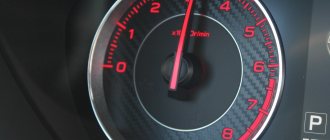
A mechanical tachometer is a rarity. These are the very first devices that were installed on cars. Its use today has no basis other than adherence to retro style. Analog tachometers are the main type that is found on the VAZ 2105. They have the form of a dial and a arrow, less often, a vertical or horizontal scale. These are the devices installed in panel 2107, but they can also be remote.
And the last type is the most modern. This is a digital tachometer. It has a lot in common with the electronic one, but the display is better. Capable of displaying several different dimensions at the same time and having a nice design. This is the most expensive type.
Injector and carburetor
Many car owners have long switched to using an injector instead of a carburetor. The tachometer of the injector and carburetor has a slight difference. But it will not work correctly, without intervention in the design.
You need to pay attention to this
Connection method
The device is selected for a specific type of engine. The connection is carried out strictly according to the tachometer instructions. The colors and purpose of the wires may vary greatly.
The most common connection is 3 wires:
- "+" to "+";
- “–” to “–” or “ground”;
- "signal" for ignition.
This connection is used when replacing the tachometer on a panel from a VAZ 2107.
The second connection is more often used on remote devices. It looks like this:
- “+” to “+”, to the terminal marked “B+”;
- “–” to “–” or “ground”;
- “signal” to the coil (contact “K”).
There are all sorts of options that allow you to use the device for your own purposes. For example, the connection determines when and how the device will turn on. The choice depends on the owner’s knowledge of the car’s electrical circuits and the flight of his imagination.
Note
The number of engine cylinders is indicated on the box of each tachometer. Accordingly, it must coincide with their number in the car. Otherwise, the readings will not be accurate.
Among the remote devices that the market offers, there are a large number of low-quality products. The error in their work can be enormous. It is better to opt for well-known manufacturers.
autodont.ru
Why do you need a tachometer?
The main purpose of the tachometer is to determine and display the number of revolutions of the crankshaft. But it also produces many other useful functions.
Among the additional functions of this element are its assistance in:
- Determining the optimal moment to change gear;
- Assistance in regulating vehicle idle speed;
- Detecting floating speeds;
- Torque determination;
- Identification at the early stages of certain malfunctions and malfunctions in the operation of the machine engine.
Why the tachometer on the VAZ 2107 carburetor and injector does not work and the needle jumps: repair and diagram
The driver can learn about the main operating parameters of the vehicle thanks to the dashboard. This device is equipped with basic sensors and indicators that indicate the operation of certain devices. One such device is the tachometer. For what reasons does the tachometer on a VAZ 2107 carburetor not work and how to replace the device - detailed instructions are described below.
Design and purpose of the tachometer
The purpose of the VAZ tachometer is to visualize the readings of the crankshaft. The device shows how fast the crankshaft rotates per minute, these readings are also called engine speed. Structurally, the VAZ 2107 tachometer is a milliammeter connected in one housing to an electronic part; these elements are installed on a printed circuit board.
As for the principle of operation, it consists in measuring the frequency of pulse transmission in the primary circuit of the engine ignition system. With the power unit operating, during one revolution of the distributor shaft, the contacts on the breaker should close and open 4 times. Accordingly, with one revolution, 4 voltage and current pulses are formed in the electrical circuit. As the crankshaft speed increases, the pulse transmission frequency also increases, which, in turn, affects the deflection of the instrument needle.
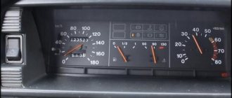
"Seven" tidy with tachometer
Possible malfunctions and ways to eliminate them
Often the cause of device malfunction is the use of inappropriate high-voltage wires. In particular, this problem usually occurs as a result of replacing them with silicone ones. Due to the use of silicone high-voltage wires, the instrument needle may begin to twitch.
As for malfunctions in which the tachometer does not work at all, the procedure for identifying them may differ depending on the type of engine:
- On carburetor engines, three wires are connected to the device. Two of them are power, and the third is connected to the coil. To determine the cause of the device failure, you need to gain access to the back of the control panel and disconnect the terminals connected to the device. Then, using the other three wires, which must be operational, the device should be connected directly to the battery, as well as the coil. When the power unit is started, the device should start working (then the reason lies in the circuit); if this does not happen, then it is necessary to look for the cause in the ignition system or the device itself.
- As for injection engines, in this case the tachometer connection diagram is somewhat different; 4 wires are used here. Two of them are power, one goes to the ECU, and one goes directly to the crankshaft sensor. The best option would be to conduct computer diagnostics. You can also try checking the condition of the contacts on the connectors or replacing the DPKV with a working one (the author of the video is minishumaher).
DIY replacement instructions
Car owners, as a rule, think about the need to service and repair the tachometer if it fails.
More information about replacing the device:
- Disconnect the battery and use a flat-head screwdriver to pry and remove the three handles installed on the heater control selector.
- Unscrew the nut securing the odometer reset lever, and also remove the washer installed behind it.
- Next, using the same flat-tip screwdriver, pry off the cap of the bolt that secures the tidy. After removing it, unscrew the screw securing the shield to the center console bracket.
- Having done this, move the right part of the tidy to the maximum, then remove the left part. After this you will have access to the back of the shield, now you need to unscrew the speedometer cable nut and completely disconnect it. Next, disconnect all hoses and connectors connected to the shield.
- Remove the dashboard. Remove the tachometer from it and install a new one. If you have connected everything correctly, the installed device will work.
Photo gallery “Dismantling the tidy”
1. Unscrew the instrument mounting bolts. 2. Unscrew the nut securing the speedometer cable. 3. Disconnect the connectors from the device and remove it.
avtozam.com
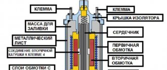
Tachometer from VAZ-2106 to the dashboard of VAZ-2105
All rights to this article belong to Mr_Ice because he is its author and performer! Many thanks to him for sending the material. And so, I decided to install a tachometer from the “six” on my VAZ 21043 (similar to the 2105). We will place the tachometer in place of the standard instrument cluster (to the left of the speedometer) and move the instruments to the beard (we will take the beard from a VAZ 2107).
And so we need: Tachometer VAZ 2106. Instruments gasoline, temperature, oil from VAZ 2106. Wire 10 meters. Beard from VAZ 2107 Watch from VAZ 2107. Pads 8 contact mother-father 2 pairs Heat-shrinkable casing. Oil pressure sensor VAZ 2106 and 2 washers for it. Oil pressure sensor splitter from VAZ 2106. Mother terminals, 5 pieces. Buttons in the beard 2107, there are 3 empty holes and they need to be plugged with something. In terms of money, all this cost me 2000 rubles (I already had a watch and a casing.) A photo of the components is attached:
- Login to leave comments
Electrical diagram of VAZ 21074
In VAZ 21074 cars, electrical energy is delivered to consumers using a single-wire circuit: the “positive” terminal of each electrical device is powered from a source, the “negative” terminal is connected to “ground,” i.e., connected to the vehicle body. This solution simplifies the repair of electrical equipment and slows down the corrosion process. All electrical appliances of the car are powered from the battery (with the engine off) or the generator (with the engine running).
The wiring diagram of the VAZ 21074 injector contains an ECM, an electric fuel pump, injectors, and engine control sensors
Wiring diagram VAZ 21074 injector
The injection versions of the “Seven” released from the factory assembly line have the following indices:
- LADA 2107–20 - in accordance with the Euro-2 standard;
- LADA 2107–71 - for the Chinese market;
- LADA-21074–20 (Euro-2);
- LADA-21074–30 (Euro-3).
The injection modifications of the VAZ 2107 and VAZ 21074 use an ECM (electronic engine control system), an electric fuel pump, injectors, control sensors and monitoring engine parameters. As a result, there was a need for additional under-hood and interior wiring. In addition, the VAZ 2107 and VAZ 21074 are equipped with an additional relay and fuse box located under the glove compartment. The additional unit is supplied with wiring that supplies:
- fuses: main relay power circuits;
- controller constant power supply circuits;
- electric fuel pump relay circuits;
relay:
- The main thing;
fuel pump; electric fan; diagnostic connector.
Additional fuse and relay block VAZ 2107 injector located under the glove compartment
Providing electricity
The G7 is responsible for providing consumers with electricity:
- Battery voltage 12 V, capacity 55 Ah;
- generator type G-222 or 37.3701;
- voltage regulator Ya112V, which automatically maintains the voltage within 13.6–14.7 V.
Diagram of the power supply system for the VAZ 21074 injector includes a generator, battery and voltage regulator
Engine starting
The starting system in the VAZ 21074 is a starter and ignition switch powered from the battery. There are two relays in the starter circuit:
- auxiliary, which supplies power to the starter terminals;
- retractor, due to which the starter shaft engages with the flywheel.
The starting system in the VAZ 21074 is a battery-powered starter with a relay and an ignition switch.
Ignition system
In early versions of the seventh VAZ model, a contact ignition system was used, which included:
- ignition coil;
- distributor with contact breaker;
- spark plug;
- high voltage wiring.
The contact ignition system of the VAZ 21074 consists of a coil, a distributor, spark plugs and high-voltage wires. In 1989, the so-called contactless ignition system appeared, the circuit of which included:
- Spark plug.
- Distributor.
- Screen.
- Hall Sensor.
- Electronic switch.
- Ignition coil.
- Mounting block.
- Relay block.
- Key and ignition lock.
In 1989, a contactless ignition system appeared, to the circuit of which a Hall sensor and an electronic switch were added. The “sevens” with injection engines use a more modern ignition circuit. The operation of this circuit is based on the fact that signals from the sensors are sent to the ECU (electronic control unit), which, based on the received data, generates electrical impulses and transmits them to a special module. After this, the voltage increases to the required value and is supplied to the spark plugs through high-voltage cables.
Outdoor Lighting
The external lighting system includes:
- Block headlights with dimensions.
- Illumination of the engine compartment.
- Mounting block.
- Glove compartment lighting.
- Instrument lighting switch.
- Rear lights with dimensions.
- Illuminated numbers.
- Exterior lamp switch.
- External lighting indicator lamp (in the speedometer).
- Ignition.
The VAZ 21074 external lighting connection diagram will help in troubleshooting headlights and tail lights
Auxiliary equipment
Auxiliary or additional electrical equipment of the VAZ 21074 includes:
- electric motors: windshield washer;
- windshield wiper;
- heater fan;
- radiator cooling fan;
cigarette lighter; watch.
The connection diagram for windshield wipers uses:
- Gearmotors.
- ED headlight washer.
- Mounting block.
- Egnition lock.
- Washer switch.
Windshield wiper motors drive a trapezoid that moves the wipers across the windshield
Tachometer sensor
Separately, it is worth considering such an element of the tachometer circuit as its sensor, or rather, the crankshaft position sensor (CPS). This device serves not only to count crankshaft revolutions, but also to determine its position at a certain moment, which is necessary for the electronic control unit to ensure proper operation of the power unit.
What is a crankshaft position sensor?
DPKV is an electromagnetic device whose operating principle is based on the phenomenon of induction. When a metal object passes near the sensor core, an electrical impulse is generated in it, which is transmitted to the electronic engine control unit. The role of such an object in the power unit of the “six” is played by the crankshaft gear. It is to its teeth that the sensor reacts.
The operating principle of the sensor is based on the phenomenon of induction
Where is the crankshaft position sensor located?
The DPKV on the VAZ 2106 is fixed in a hole on a special boss of the camshaft drive cover in the lower part of the engine next to the crankshaft gear. The wiring harness going to it can help determine its location. The sensor itself is enclosed in a black plastic case. It is attached to the timing cover with one screw.
The hole for mounting the sensor is marked with a blue arrow
How to check DPKV for performance
In order to determine whether the sensor is working, there are two methods. For this we need:
- wrench 10;
- screwdriver with Phillips bit;
- multimeter
The verification process consists of the following steps:
- Using a 10mm wrench, loosen the negative terminal on the battery. Let's take it off.
- Raise the hood and find the crankshaft position sensor.
- Disconnect the connector from it.
- Using a screwdriver, unscrew the screw securing the device.
- We remove the sensor.
- Turn on the multimeter in voltmeter mode with a measurement limit of 0–10 V.
- We connect its probes to the sensor terminals.
- With an energetic movement, we bring the blade of a screwdriver near the end end of the device. At this moment, a voltage jump of up to 0.5 V should be observed on the device screen.
- Switch the multimeter to ohmmeter mode with a measurement limit of 0–2 KOhm.
- We connect the probes of the device to the sensor terminals.
- The resistance of the sensor winding should be in the range of 500–750 Ohms.
If the device readings differ from those indicated, the sensor is faulty and must be replaced. The device is replaced in accordance with paragraphs. 1–5 of the above instructions, only in reverse order.
Replacing the tachometer VAZ 2106
If a malfunction is detected in the tachometer itself, it is hardly worth trying to repair it yourself. Even if he earns money, it is not a fact that his testimony will be correct. It is much easier to buy and install a new device. To replace the VAZ 2106 tachometer you will need:
- flat blade screwdriver;
- pliers;
- pencil, felt-tip pen or marker.
To replace the tachometer, you must:
- Remove the instrument panel trim by prying it off with a screwdriver.
- Move the panel to the side.
- Disconnect the wiring harness block from the device, as well as the connectors of additional wires, having previously marked their location with a marker or pencil.
- Using your hands or using pliers, unscrew the nuts securing the tachometer to the panel.
- Remove the device from the cover.
- Install a new tachometer and secure it with nuts.
- Connect and install the panel in reverse order.
As you can see, the tachometer is not such a sophisticated device. There is nothing complicated either in its design or in the connection diagram. So, if problems arise with it, you can easily deal with them without outside help.
Replacement
If a malfunction is detected on the revolution counter itself, it must be replaced. This mechanism cannot be repaired. To replace you need:
- Disconnect the “+” terminal from the battery.
- Remove the heating control knobs.
- Unscrew the odometer mounting nut.
- Unscrew the mounting bolt at the top of the dashboard.
- Pull the instrument panel towards you.
- Disconnect all electrical connectors, wires and speedometer cable.
- Disconnect the tachometer power plug.
- Pull out the instrument panel completely.
- Unscrew the two tachometer mounting nuts.
- Install and secure the new part.
Everything else must be assembled and secured in reverse order. After installation and assembly, you need to connect the terminal to the battery, start the engine and check the operation of the new tachometer.
Tachometer does not work
If the tachometer does not work, we recommend starting by checking the connection of the wire to terminal “K” of the ignition coil. If the connection is working and there are no breaks, then you will have to remove the gearbox. We ring the wire from contact “K” to the third terminal of connector “A” and check the reliability of this contact.
If this contact is working, then we check the printed conductor between the mating part of the connector and the resistor in the starting circuit with a nominal value of 91 kOhm, then we go to contact “1” of the tachometer. Also check the plus and minus of the battery. If the car is fuel-injected, then check the circuit between the ignition module and the fifth contact “A” of the gearbox and then with the first contact of the tachometer.
The main reasons for tachometer failure
Often, tachometer malfunctions appear as a result of replacing standard high-voltage ignition wires with silicone ones. In this case, the arrow begins to twitch. Its failures to zero are typical. The fact is that standard wires have a different linear resistance, so the shape of the pulse changes on the coil winding. Reduce the value of the external resistor on the control board.
On injection-type machines, you can improve the performance of the tachometer by connecting a 200...1000 pF ceramic capacitor to the gearbox board between the wires of contacts “1” and “minus”. It is worth noting that such manipulations cannot be performed on carburetor-type cars, since the tachometer in this case will simply stop working.
If a malfunction is not detected during the above manipulations, you will have to disassemble the gearbox and look at the board.
We analyze the CP as follows:
- Remove the daily odometer reset handle from the axle.
- Unscrew the screws securing the gearbox visor to the body and securing the tachometer.
- Disconnect the wires from the tachometer.
- Unscrew the screws securing the backlight cable.
- We unscrew the three nuts of the temperature indicator and remove them together with the washers.
- Remove the visor along with the protective glass.
- Remove the arrow from the tachometer by prying it off with a screwdriver.
- On the gearbox scale near the tachometer needle, unscrew the two screws.
- We push the temperature indicator pins out of the holes in the board.
- We slightly bend the gearbox scale and remove the tachometer.
www.vsepoedem.com
Install a tachometer on a VAZ 2105: why, how and why
The standard instrument torpedo of the VAZ 2105 is not equipped with a tachometer. This unit allows drivers to monitor the crankshaft speed of the vehicle engine. Experienced auto mechanics know how to install a tachometer on a VAZ 2105.
Part selection rules
An important device for cars
You can install this unit yourself. To do this you will need the following tools and materials:
- screwdrivers,
- wiring diagram,
- keys,
- insulating tape,
- wires.
First you need to find out the operating principle of the unit in question. The pulses read by this device enter the ignition system coil, displaying information on the screen. Auto mechanics recommend buying an electronic tachometer. When choosing this device, you should take into account the structural features of the VAZ 2105. Otherwise, the tachometer will show revolutions with a slight error. You can install a universal unit with switches. To do this, connect it to any type of engine.
In the selection process, you should also take into account the fact that there are dial and electronic tachometers. You can install a tachometer on a VAZ 2105 of the first type with a tuner. The second type includes the Balsat TX-319t model. It is a microprocessor device, the main task of which is to monitor the operation of the “five” engine. If necessary, the driver can select the most suitable mode. Before you figure out how to install a tachometer on a VAZ 2105, you need to take into account the capabilities of the car:
- measurement of crankshaft revolutions of 2-6 and 8-cylinder engines,
- availability of watches,
- ability to remember maximum and minimum temperatures,
- presence of a stopwatch,
- ability to measure crankshaft acceleration.
Installing an electronic tachometer involves independently adjusting the backlight. The advantages of the Balsat TX-319t among auto mechanics include the presence of a standby mode. This feature significantly reduces energy costs.
Installation of the device
How to connect a tachometer of this type is of interest to many VAZ 2105 car owners. First, select a mounting location. The negative wire is then connected to the vehicle body. The plus wire is connected to the corresponding ignition terminal. A voltage of 12 W appears in it.
The backlight allows you to see the speed at any time of the day, so auto mechanics recommend installing just such units. Before starting work, you need to figure out how to connect a tachometer of this type. For this, an appropriate scheme is used. The backlight wires are connected to the side marker switch. If the car is of an injection type, then the device is connected to the controller of the electronic engine control system. In this case, reading is performed from the last element. Installing a tachometer from another vehicle is prohibited, as difficulties may arise in the operation of the mounted unit.
Tachometer installation instructions
The tachometer on the VAZ 2105 is installed on the torpedo 2107, or the device is removed as a separate element. The second method involves using a housing to fix it to a panel or glass stand. This case is sold in specialized stores or made by yourself. For this, improvised means are used.
You can use the device from 2106. It is equipped with the required connection connector. The “five” wiring does not have this option, so it is recommended to cut off the terminal contact, leaving only the wire. If necessary, the wires are extended in order to connect them to the ignition coil. This procedure is carried out in the following order:
- the brown wire goes to the “plus” of the coil,
- orange - to the terminal marked “B+”,
- black and white is attached to the vehicle body.
The electronic tachometer can be installed anywhere. This device has 3 wires going to the ignition coil, ground and terminal. It is necessary to take into account that on such a unit there is a marking of conductors.
https://youtube.com/watch?v=FGcnnXpS468
If a 2107 torpedo is used, you will need to remove the standard instrument panel. To do this, the screws are unscrewed and the chips are disconnected. On the back of the panel, the nuts are unscrewed, with the help of which the torpedo is attached to the body. The fastening from below is released in the same way. Then the stove and ashtray are removed. When installing a new panel, the steps are performed in the same way. Moreover, the 2107 torpedo is already equipped with a tachometer.
This device is connected as follows:
- The 1st wire goes to the “plus”,
- The 2nd is connected to the “minus”,
- 3rd - to ignition.
Typically, VAZ 2105 drivers install a tachometer in order to be able to keep track of the time and control the voltage in the network.
Installing a tachometer on a VAZ 2105i — Lada 2105, 1.6 l., 2010 on DRIVE2
It was evening, there was nothing. After purchasing the tachometer, my hands were itching to connect it. Why would such a thing lie idle on a shelf?! In addition, there were some mythical doubts about whether it would fit or not. Where to begin. Naturally, you need to start by reading the manual. (in my case, from looking at the packaging =))
And so we open the box, take out another box, take out the treasured bag, take out the piece of paper and what do we see? What we see is that we shouldn’t have skipped English lessons at school. Not just one Russian letter.
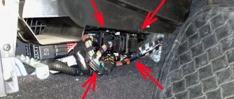
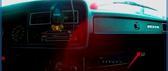
But it is worth noting, however, the absence of Chinese characters, which in itself cannot but rejoice. In principle, if you really try to remember what you taught at school, you can intuitively guess that green is a signal from the ECU (ECU), black is for ECU ground, red is for + the ignition switch, and orange is the backlight. Everything is elementary simple. although there are a lot of things written there, all sorts of NOTE, Warning, DO NOT START ENGINE and other scary inscriptions in Latin letters, but the main thing is still 4 wires)) In the store they gave me a business card for the installation service, of course I could contact them, but there is a crisis outside and to I had no desire to go there. but then everything went like clockwork; we connect each wire; if with 3 everything is less clear, then with the fourth, namely the green one, you shouldn’t make a mistake. There is a red sticker on it, and lo and behold, it says in RUSSIAN not to connect to + do not connect to + coils, etc. open the VAZ 2107i diagram and see where the pulse signal to the tachometer comes from. There is a chip next to the ECU (3x3 round holes)
we find it and see that the “brown-red” wire comes in and doesn’t go anywhere. As a friend told me, feel free to connect such a wire throughout the domestic auto industry and you will be happy... And so it was done. After connecting, the question became where to put it; naturally, it should be placed in the instrument panel. Lo and behold, there are two quite important sensors, where should we put them? No where yet. After sitting and thinking about turning off the tachometer, I didn’t want to replace it, so I put it, like many others, in the middle of the dashboard. It doesn’t look important, I would say childish, but on the back it looks like a home clock. so I installed it as temporarily as possible until I find three sixth sensors and then I’ll stuff it into the dashboard...
teaser or first fitting))
Self-production
The remote tachometer is needed for the same thing as the one integrated into the panel - to display the crankshaft speed. It can be made for both four-stroke and two-stroke engines. The latter is relevant for old mopeds or motorcycles. There are two ways to get yourself a remote tachometer:
- Buy ready.
- Do it yourself.
Having done it yourself, you can be confident in its performance and the accuracy of its readings. The fact is that very cheap remote tachometers, as a rule, lie very much. But more expensive ones are not affordable for everyone. It is in this case that it will be convenient to make a homemade tachometer.
Manufacturing process
As we already understood, it happens that the tachometer is simply missing. In this case, you will have to do your own production. You can find a lot of instructions on the Internet, but we have developed the most optimal one and described in detail how to do everything correctly and accurately.
So, let's start by collecting the necessary tools and parts. We will need:
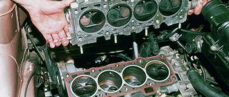
- Engine tachometer mechanism from a suitable car (for example, from the same car, but the version where the tachometer was installed).
- A tin can or any suitable size case.
- Metal scissors.
- Glue, polyurethane foam and paint.
- Spatula, putty and tape.
- Hairdryer and sharp knife.
First we need to fit the housing tightly to the engine tachometer mechanism so that there are no backlashes. If the mechanism is deeply recessed into the body, then you will have to cut off all the excess with scissors to make it look beautiful. It will be necessary to cut so that there are no jagged edges or sharp edges. If a sharp edge accidentally comes out, you will have to grind it to a smooth surface.
Now we fill the inner cavity of the body of the future engine tachometer and the outer surface in the place where it will be attached to the panel with polyurethane foam. After the foam has dried, you can use a knife to give the body any beautiful shape. Inside, you need to make the space so that the mechanism sits tightly and does not move. You also need to remember about the holes for the wires. Try the case on the panel in advance and think about how the wires will be laid and where it will be more convenient to make these same holes.
To do this, we cover it with fiberglass and fill it all with epoxy glue. The glue must be allowed to dry for at least a day; further work cannot be started yet - the workpiece may be damaged. Now you need to putty the engine tachometer blank. You need to devote maximum time to this stage, since painting will come next and the workpiece should be as even and smooth as possible so that everything looks decent. In principle, you can paint it any color, but preferably the color of the car panel on which the engine tachometer will be located.
If the tachometer for a two-stroke motorcycle will always be on the street, then the paint will have to be chosen as resistant as possible so that it can withstand all possible weather changes and the characteristics of the motorcycle’s operation. That's it, now you need to place the mechanism inside the case, remove the wires and connect them to the machine. After checking, if everything is fine, then glue the body to the selected location on the panel.
Types of tachometers
There are purely mechanical devices, as well as:
The first is a very old option. It makes no sense to use it due to imperfection and low accuracy.
For the “five”, the best choice would be an analog mechanical-electrical tachometer designed for the 2107 model. If you decide to change the entire panel, then we recommend staying with this option. For those who like the native shield, analogue remote instruments are available.
The electronic type does not have classic hands, but a display. All data is displayed in the form of numbers, which is very convenient. There is only one drawback to such products - the delivery of information with a slight delay.
The digital tachometer is the most modern. According to the principle of operation, it is similar to an electronic one, but has a number of additional functions (clock, calendar, etc.) and looks more attractive.
Connection diagram for tachometer VAZ-2108 and 2109
Let us immediately note that the fuel supply system – injector or carburetor – does not play a special role here. As you know, currently the most common are cars with the following engine types: gasoline or diesel. Depending on this, the tachometer is selected, unless, of course, it comes in the stock version. The thing is that on gasoline engines the tachometer reads data from the ignition coil, or rather, the impulses that arise here. However, the design of diesel power plants does not provide for this unit. Accordingly, here the tachometer reads pulses not from the ignition coil (for lack of one), but from the generator.
The first two wires (12-volt and Signal) are to contacts “B” and “K” of the ignition coil, respectively. All that remains is to secure the mass in any convenient place.
Useful: Wiring diagram for a double switch for 2 light bulbs in a chandelier
Why does the VAZ tachometer jump?
It often happens that the needle starts to twitch. If the car is fuel-injected, then troubleshooting involves connecting a diagnostic scanner and checking the engine systems. Jumps in the TX-193 needle in most cases are also a symptom of malfunctions associated with its electrical circuit. The reasons for this behavior of the device may be:
- lack of good contact at the negative terminal of the battery;
- oxidation or burning of the brown wire on the ignition coil;
- burning or wear of the contacts of the ignition distributor cap or slider;
- wear of the distributor shaft bearing;
- shorting the red wire powering the device to vehicle ground;
- malfunction of the crankshaft position sensor (for injection engines).
A similar problem is solved by stripping the contacts, replacing the ignition distributor cap, slider, support bearing, restoring the integrity of the insulation of the device’s supply wire, and replacing the crankshaft sensor.