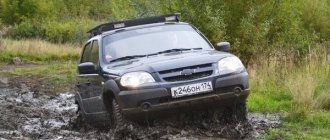
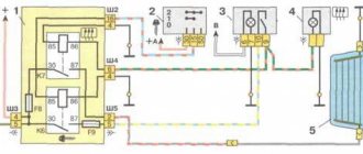
Many people are interested in how to center the transfer case on the Niva.
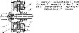
There are enough reasons for such interest. The transfer case mounting on this VAZ creation leaves much to be desired. Of course, the transfer case does not fall on the road, but it can cause quite a lot of inconvenience. Therefore, drivers strive to learn how to solve alignment problems on their own, without the participation of a car service center. In fact, centering is a fairly simple job. You just need to know the correct algorithm of actions. Otherwise, there shouldn’t be any difficulties; after all, the Niva is a simple car and is designed for garage service. How to center the transfer case on a Niva? First you need to decide why this is being done. To understand this, you need to understand the technical features of this unit. The transfer case is attached to the body using special brackets. It is this fastening that is to blame for the misalignment. For some reason, domestic engineers did not realize that a simple threaded fastener could become loose. This causes the box to shift relative to the gearbox. This causes vibration, which is the first sign that the transfer case needs to be centered.
How to center the transfer case on a Niva? Method for shorty and Chevrolet
Many people are interested in how to center the transfer case on the Niva. There are enough reasons for such interest. The transfer case mounting on this VAZ creation leaves much to be desired. Of course, the transfer case does not fall on the road, but it can cause quite a lot of inconvenience. Therefore, drivers strive to learn how to solve alignment problems on their own, without the participation of a car service center. In fact, centering is a fairly simple job. You just need to know the correct algorithm of actions. Otherwise, there shouldn’t be any difficulties; after all, the Niva is a simple car and is designed for garage service. How to center the transfer case on a Niva? First you need to decide why this is being done. To understand this, you need to understand the technical features of this unit. The transfer case is attached to the body using special brackets. It is this fastening that is to blame for the misalignment. For some reason, domestic engineers did not realize that a simple threaded fastener could become loose. This causes the box to shift relative to the gearbox. This causes vibration, which is the first sign that the transfer case needs to be centered.
Centering method
To carry out this work you will need a lift, although with some skill you can get by with simple supports. First you need to prepare the car. If there is a lift, it is raised up. If supports are used, the corners of the machine are jacked up one by one and it is placed on them. Please note that all supports must be stable, otherwise the work will be unsafe. You should also prepare the tool in advance. If there are no plans to simultaneously replace other parts, then it is quite possible to get by with a ratchet and a “13” head. During operation, an assistant must be in the cabin.
Adjustments are made in the following order:
- To begin with, you should evaluate the condition of the splines on the cardans. If they are very worn, then most likely you will not be able to perform the alignment correctly. In case of significant wear, parts should be replaced;
- The transfer case mount is inspected. Often the displacement can be seen with the naked eye;
- Next, loosen the transfer case mount. Just don’t unscrew it completely;
- After this, start the engine and “accelerate” the car to a speed of 80-90 km/h. In this case, the transfer case will fall into place on its own;
- The crucial point is to consolidate the result obtained. This can be achieved in 2 ways. Mechanics argue which one is better, but both are used in everyday life. Most often, the engine is turned off, and with its help the transfer case and cardan shafts are stopped.
- All that remains is to quickly tighten the nuts. Disadvantage here 2. Stopping the box in this way can have a negative impact on its condition.
- Also, you need to tighten the fastener as quickly as possible, otherwise it will be of no use. A more reliable, but technically complex method is to tighten with the engine running;
- The car is lowered to the ground and testing is performed.
If the vibration persists, the procedure should be repeated.
Eliminating prerequisites
The misalignment of the transfer case occurs due to an undeveloped design. Therefore, many craftsmen strive to modify the fastening so as not to bother with alignment once a year. A special frame is used for this. In recent years, it can be purchased in stores, but you can also make it yourself.
The advantages of this modification are the following:
- The transfer case is mounted on the rigid base of the subframe. The attachment to the body is made through a subframe, this allows to reduce the level of vibration transmitted to the body;
- It plays the role of a kind of protection for the crankcase;
- Also worth mentioning is adding additional rigidity to the side members.
- Among the disadvantages, we can mention a slight decrease in clearance. Although, in light of the advantages, this does not play a special role.
To assemble the subframe you will need a square pipe.
Some people use a corner, but in this case the structure will be less durable. The support plates are made of sheet steel. Before assembly, you should cut off the old transfer case mounting bolts. Now it will be installed on the subframe. The pipe is cut to size and the frame is welded. After that, holes are drilled in the crossbars for fastening the transfer case. It is important not to make a mistake with the sizes. The next step will be assembling the mount to the body. Sheet steel support plates are welded to the subframe. Holes are drilled in it. After fitting, you need to drill holes in the floor of the car.
For fastening, use M12 bolts and thick washers. After installing the subframe, do not forget to treat it with an anti-corrosion compound. This will increase the service life of the part. This is how, through simple manipulations, you can get rid of one of Niva’s sores.
Conclusion. Even great cars have flaws. The domestic SUV Niva is no exception. During active use, vibrations emanating from the transmission may occur. That’s when the question arises of how to center the transfer case on the Niva. In fact, this work is not difficult, but there are some nuances that are better to know before starting work. Some people, knowing this feature of this car, install a subframe, this can significantly reduce the noise of the transmission.
Is it really worth changing the transfer case?
I took a radical approach to the issue of eliminating excess noise in the Niva’s cabin. I often drive my family, so I simply installed a new small-module transfer case. The front and rear covers were equipped with 2-row bearings; this innovation was introduced at the Tolyatti plant back in 2010. Thus, the output shafts eliminated unnecessary vibrations, and in general, the service life and reliability of the entire RK mechanism increased.
I also simultaneously replaced the levers with ones that have anti-resonance bushings installed inside them. A lever of a similar design, by the way, was originally installed from the factory on the Chevy Niva (it has only 1 lever), which is why the howling and hum characteristic of the classic Niva were usually not noticed on the Shniva.
Repair of transfer case on Niva 21213, how to center it, do-it-yourself adjustment with video
The transfer case of the Niva car and some other SUVs is designed to distribute the torque of the wheels both between the axles and between different wheels of the same axle. This is done in order to increase cross-country ability on particularly difficult sections of the route. In the language of specialists, this device is called a “demultiplier.”
Transfer case location and functions
Location of the transfer case in the Niva 21213
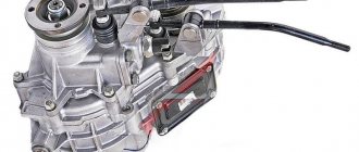
The transfer case occupies an intermediate position in the vehicle transmission between the gearbox and the driveshaft. It has its own body in which its components are located.
The transfer case helps to implement such SUV capabilities as:
- Center differential lock.
- Disabling the drive axle.
- Increased torque of the drive wheels.
- Distribution of torque along the wheel axles.
Possible signs of malfunction
A violation of the normal operation of the VAZ-21213 transfer case can be assumed by the following signs:
- Delays when connecting front-wheel drive.
- Transfer case overheating.
- High transmission oil consumption.
- Spontaneous disconnection of the front axle.
There is nothing fundamentally complicated in the design of the multiplier, except that it itself is not attached to the main gearbox as on more modern all-terrain vehicles. Intermediate driveshafts extend from the transfer case to the manual transmission. The rest of the device is represented by gears, satellites and bearings. The design also includes a free differential with locking.
Tools
- Spanner 13.
- Flathead screwdriver.
- Key for 10.
How to remove a box from a car
- The machine must be installed on an inspection hole or lift.
- The transfer case levers are set to the neutral position.
- The lining of the central floor tunnel is removed.
The tunnel cover must be removed to gain access to the transfer lever hatch - The handles and lever covers are removed.
The handles and covers of all levers can be carefully removed - The lever hatch cover is removed using four screws.
We get access to the insides of the transfer case - The speedometer drive is disconnected from the transfer case.
You need to remove the sensor connected to the speedometer from the transfer case. - The driveshafts are removed from the front and rear.
Cardan shafts fit to the transfer case front and rear - After unscrewing several fasteners, the transfer case housing is removed.
It’s enough to just push it forward a little (if you look in the direction of the car’s movement, backward) and down. We push with one hand and hold with the other. When removing the box, the main thing is not to overdo it
Installation, centering and adjustment
- Install the engine mount brackets correctly.
- Install the transfer case without fully tightening the bolts of its fastenings.
- The flanges of the drive shaft of the box must coincide with the intermediate driveshaft.
- Install the transfer case supports and secure the fasteners.
- Connect the transfer case to the front and rear universal joints, and reinstall the differential lock sensor.
Centering the range multiplier can be done in different ways. The classic version of alignment is that the car is installed on a lift or inspection hole, and all operations are performed by two people, one of whom is sitting behind the wheel. The procedure is performed as follows:
- Fourth gear is engaged and the lock is disabled.
We put the transfer case in neutral position, engage the 4th gear of the manual transmission - The transfer case mounting nuts are loosened under the car.
To center the range-multiplier, use a 15mm wrench to loosen the fastenings - The driver begins to accelerate the engine, informing his partner about this, who directs the box to the desired position.
The assistant gets all the brunt of the alignment work; strength and dexterity are needed here.
Repair and alignment of the transfer unit must be carried out subject to the presence of experience and knowledge in the field of design and repair of the specific transmission of all-wheel drive vehicles. The range-multiplier needs to be centered after each reinstallation. The correct position of the box is judged by the presence of vibration.
- Author: Konstantin Kostin
Understanding the terminology
Let's start by diving into the materiel. Transfer case (TC) is a separate unit of an all-wheel drive vehicle, which provides multi-mode power distribution from the engine to the front and rear axles.
Externally, this is a mechanism located under the bottom of the car, in the body of which a multiplier (divider) is placed in series to obtain an intermediate gear ratio in the transmission and a splitter of one power flow into two. It is with the help of this device and its controls (levers) that go into the vehicle interior that the LADA 4×4 driver selects the all-wheel drive operating mode.
The RK directly connects the front driveshaft and the intermediate shaft (shaft) with the vibration damper to the vehicle’s gearbox. As is probably already clear from the description, this element is connected to the rear axle of the car via a rear propeller shaft.
Transfer case 2123 (2-row bearing) Chevrolet Niva Art. 21230-1800020-0116500.00-+ Buy
Transfer case 2123 Chevrolet Niva Art. 21230-1800020-0114500.00-+ Buy
Transfer case (2-row bearing) 21213 Art. 21213-1800020-0115000.00-+ Buy
Transfer case height alignment — Lada 4×4 3D, 1.7 l., 1995 on DRIVE2
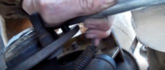
Hello everyone! When I was patching the bottom, I cut off the transfer case mounting bolts, welded a thicker plate, drilled it through the old holes, inserted new bolts and grabbed them for welding. And what happened, what happened was that when I tightened the transfer case, the original floor sank in because... The new plate did not lie tightly. This means that you need to center it, and here’s how I did it. I screwed two pieces of wire onto the drive shaft, adjusted them so that the ends came together end-to-end when you lift them up, then twist the drive shaft and look, I got a gap of about 7 mm at the bottom. Since I didn’t find anything except thick paronite, I had to cut it. First I placed one plate at a time, and saw that the gap had become approximately half as large, then I placed another one at a time. Let's check... Now the wires don't diverge, at least I didn't notice it with my eyes! Now the transfer case is centered in height. Then I put the car on chocks, loosened the transfer case mounting nuts, accelerated it to 80 km/h using a choke and tightened the nuts. Let's hope that the vibration will become less!
All the best!
Removing the howl and hum
We will assume that we have dealt with the vibration, but an equally significant problem remains - how to remove the howling of the transfer case on the Niva. Vibrations of the mechanism are not always the only reason for the appearance of extraneous irritating sounds. And the characteristic noise of the transfer case, alas, is one of the “trademark” shortcomings of one of the best domestic SUVs.
- The first thing you should pay attention to is the levers. It is better to immediately replace them with silent ones - with anti-resonance bushings inside. They won’t eliminate all the noise, but they will definitely extinguish some of it.
Silent transfer case levers NIVA 2121 black Art. SV-21-18040401400.00-+ Buy
- The result will be even better if you install a small-module transfer case - with front and rear covers equipped with double-row bearings. In 2010, AVTOVAZ introduced new double-row bearings for output shafts in order to get rid of backlash and runout, as well as extend the life of the seals and, in general, increase the reliability of the mechanism. Here logic is man’s friend: less shaking and hesitation means higher service life and reliability.
Transfer case (2-row bearing) 21213 Art. 21213-1800020-0115000.00-+ Buy
Niva transfer case. Ways to eliminate vibration
Home » Car repair » Add to bookmarks
The Niva family of cars differs from VAZ passenger cars in permanent all-wheel drive - they have two drive axles. In total, the VAZ SUV has three differentials in its transmission - one for each axle and another center differential.
The Niva transfer case is designed to distribute traction forces between axles, and operates on the principle of a 2-speed gearbox.
The device of the VAZ Niva transfer case
The transfer case is not present in all VAZ passenger cars, but only on cars with two drive axles. In the transmission, the transfer case (TC) is installed at the rear of the gearbox; a rear driveshaft is attached to its shank, which connects the transfer case to the rear axle. The front axle is also driven by the steering wheel; it is connected to the transfer case by a front driveshaft.
The reduction gear in the Republic of Kazakhstan is designed to obtain high torque, it is used to overcome difficult sections of the road, and helps to cope with off-road conditions. The VAZ Niva transfer case contains the following main parts:
- the body itself;
- front axle drive shaft;
- intermediate shaft;
- drive shaft;
- gears;
- bearings;
- differential housing;
- satellites;
- differential lock clutch;
- gear shift clutch;
- flanges (for connection to cardan shafts);
- oil seals;
- control levers.
Transfer case Niva 21213
Model VAZ-21213 is an all-terrain passenger car with permanent all-wheel drive and differential lock. Brand 21213 is a restyled version of the first VAZ SUV, VAZ-2121. RK Niva 21213 has three gears:
- the first - with a gear ratio of 1.2;
- the second, lowered – with the number 2.135;
- neutral
21213 is equipped with 4-speed and 5-speed gearboxes, and when the first speed of the transfer case is turned on, the car operates in standard mode, the gear ratios in the transmission are from 5-speed. The checkpoints are as follows:
- 1 – 4,4;
- 2 – 2,52;
- 3 – 1,63;
- 4 – 1,2;
- 5 – 0,98.
When you turn on the second position of the transfer case lever (reverse position), the gear ratios change (lower):
- 1 – 7,83;
- 2 –4,48;
- 3 – 2,90;
- 4 – 2,14;
- 5 – 1,75.
On ordinary roads, the transfer case is always in first gear, the transfer case control lever (reduction gear) is pushed forward. The neutral gear of the RK disconnects the transmission, and in this position the car does not drive; there is also a neutral in the gearbox.
Motorists often ask the question: why is neutral gear needed in a transfer case? The neutral is used when connecting additional units to the transmission, for example, a mechanical winch; in this case, a power take-off must also be installed.
Transfer case Niva 21214
On Niva cars (with the exception of Chevrolet Niva) two main types of transfer cases are used:
- 21213 (modifications 21213-1800020-01 and 21213-1800020-02):
- 21214 (modifications 21214-1800020-01, 21214-1800020-02, 21214-1800020-10).
The transfer cases have almost the same design among themselves - the RK 21214 additionally has a speed sensor drive.
Transfer case Niva Chevrolet
The transfer case of the VAZ 2123 car has fundamentally the same device as unit 21213/21214, but in the Chevy Niva:
- different control mechanism (with one lever);
- an additional support was installed (on a simple Niva the RK is mounted on two supports, on a VAZ 2123 car - on three supports).
Malfunctions of VAZ transfer cases
The transfer case on the Niva is a fairly reliable unit; problems with repairs in the mechanism itself arise mainly due to insufficient oil level in the valve - if for some reason the oil leaks out, intensive wear of all parts occurs. Among the frequently occurring malfunctions are:
- vibration in the body at various speeds when the car is moving;
- vibration when the vehicle starts moving;
- noise in the transfer case when the car is slipping or turning;
- difficult upshift or downshift, difficult engagement of the lock.
Vibration
Vibration in the body is the main “disease” of the Niva; it often occurs due to improper alignment of the transfer case. Most often, vibration occurs on VAZ 21213/21214 cars, since the transfer case is mounted only on two supports on the sides of the body; on the Chevrolet Niva, the transfer case is already installed on three supports. But before you start adjusting the position of the transfer case, you should check the condition of other parts of the chassis - vibration can occur for other reasons:
- driveshafts are poorly secured;
- wheels are not balanced;
- there is play in the cardan crosspieces (vibration is especially affected by play in the rear driveshaft crosspieces);
- The vibration comes from the engine itself.
Vibration when starting off on a Niva can also occur for the following reasons:
- the mounting supports of the transfer case have become loose;
- The rubber on the RK supports themselves broke.
Transfer case alignment
Correct installation of the transfer case can be done in several ways. Most often in auto repair shops, repairmen use the following method:
- hang the car on a lift;
- loosen the transfer case;
- start the engine;
- engage the gear and accelerate the car according to the speedometer to the speed at which vibration occurs (often it occurs at speeds from 40 to 80 km/h);
- without using the brakes, reduce the engine speed, then turn off the ignition.
The transfer case itself is centered in place, all that remains is to tighten the fastenings of the supports.
You can also adjust the position of the RC using a wire; we do it as follows:
- loosen all four fastenings of the transfer case supports;
- fasten one end of the wire to the rubber coupling of the propeller shaft;
- we attach another piece of wire to the CV joint, bring the other ends of the wire to each other;
- rotate the shaft; if the transfer case is not centered, the ends of the wire will diverge during rotation;
- the task comes down to installing the transfer case using the selection method so that the ends of the wire practically do not diverge from each other in any position when turning the shaft.
Eliminate vibration with additional fasteners
Installing the third support of the transfer case on VAZ 21213/21214 vehicles allows you to reduce the level of vibration of the transfer case; with this support it is easier to center the transfer case. The part can be purchased at auto stores or made yourself. The finished product comes with three long studs (for model 2121); to install the third support on this machine, you will need to unscrew the short studs from the transfer case housing and install new studs from the kit. We carry out repairs as follows:
- dismantle the front passenger seat in the cabin;
- remove the floor tunnel lining;
- in the cabin we move aside the carpet covering the body amplifier (in front of the handbrake lever);
- remove the transfer case (alternatively, you can simply hang it up, but removing the third support makes it easier to install);
- We attach the bracket of the new support to the body of the RC;
- we install the transfer case in place, center it in the optimal position, and fasten the side supports;
- we combine the third support with the body, drill two holes in the bottom;
- Using washers, bolts and nuts (from the kit) we attach the support to the bottom of the body.
Vibration is eliminated more effectively by installing a subframe under the transfer case. You can also make such a device yourself or buy a finished product at a car store.
In order to install the subframe, the transfer case must be removed. It is more convenient to carry out such work in a pit; we carry out repairs as follows:
- leave the car in neutral gear;
- disconnect the propeller shaft from the transfer case, it is advisable to mark the driveshaft flange and the drive shaft so that during installation, align the driveshaft according to the marks - this way, the occurrence of unnecessary vibrations is eliminated;
- dismantle the muffler mounting bracket;
- remove the gearbox traverse;
- jack up the transfer case, remove the side fastenings of the transfer case;
- We treat the places where the subframe fits to the body with Movil;
- place the subframe on the gearbox studs;
- we mark the attachment points of the subframe on the side members, drill holes, attach bolts to the body;
- we tighten all fastenings, except for the transfer case supports themselves;
- we perform alignment of the steering wheel;
- Finally tighten the transfer case supports.
It should be noted that installing an additional support or subframe on the steering wheel does not always lead to the desired effect; in some cases, vibration only increases.
Removing the Niva transfer case
To repair the transfer case on a VAZ 21213 (21214), the unit must first be removed. We carry out removal in the following order:
- in the cabin we dismantle the plastic lining of the gearbox and gearbox levers;
- unscrew the knobs of the transfer case shift levers, remove the casing under them;
- disconnect the speedometer cable, for RK 21214 you will need to additionally disconnect the speed sensor;
- we unscrew the bolts with nuts securing the elastic coupling of the front and rear propeller shafts; in order to remove the bolts, the cardan shafts must be turned - they are removed one at a time in one specific position of the shaft;
- We install a jack (or other support) under the transfer case and mark the places where the side supports of the RC were attached. This is done in order to minimize the alignment of the transfer case during installation;
- unscrew the 4 nuts securing the gearbox to the gearbox;
- unscrew the 4 fastenings of the RC supports to the car body;
- Now all that remains is to dismantle the transfer case.
(1 ratings, average: 5.00 out of 5)
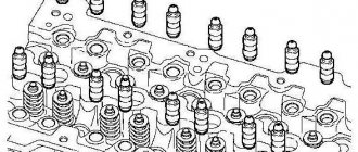
Disassembly
1 — front axle drive housing; 2 — crankcase cover; 3 — speedometer drive housing fig. 3-39fig. 3-38
rice. 3-38fig. 3-39
1- intermediate shaft; 2 - drive shaft; 3 — differential; 4 - front cover
1 - flange; 2 — oil seal; 3 — thrust ring of the bearing, 4 — front bearing; 5 - drive shaft; 6—high gear; 7 — hub; 8 - coupling; 9 — low gear; 10 — bushing: 11 — rear bearing; 12 — bearing installation ring; 13 — intermediate shaft bearing; 14 - intermediate shaft
- remove the lock ring 1 (Fig. 3-45) and spring washer 2 of the front bearing;
- remove the rear and front bearings from the differential housing (Fig. 3-46), using a universal puller and stop 67.7853.9559;
- by turning the bolts of the differential housing, separate the housing;
- remove the differential driven gear;
- remove retaining rings 8 (Fig. 3-45) and spring washer 14, then press out the pinion axis and remove the satellites and drive axle drive gears with support washers.
Also interesting: Adjusting VAZ 2114 and 2115 headlights: tips and tricks
1 - retaining ring; 2 - spring washer; 3 - bearing mounting ring; 4 — differential housing bearings; 5 — driven gear; 6 - front differential housing; 7 — front axle drive gear; 8 — retaining ring of the satellite axis; 9 — satellite; 10 — rear differential housing; 11, 15 — support washer; 12 — rear axle drive gear; 13 — satellite axis; 14 - spring washer
We recommend: Chip tuning: high-quality car acceleration and saving resources
1 — puller A.40005/1/6; 2 — stop 67.7853.9559; 3 - bearing
- the axial clearance of each axle drive gear should be 0-0.10 mm, and the moment of resistance to rotation of the gears should not exceed 14.7 N m (1.5 kgf m). If the gap is increased, replace the support washers with others of greater thickness; if the specified gap cannot be obtained when installing support washers of the greatest thickness, replace the gears with new ones due to their excessive wear;
- The drive and intermediate shafts are installed in the transfer case housing simultaneously (see Fig. 3-47);
- Press the bearings onto the differential housing using mandrel 67.7853.9558 (see Fig. 3-48);
- Before installation in covers and crankcases, lubricate the working surfaces of the oil seals with LITOL-24 grease;
- Tighten threaded connections to the torques specified in Appendix 2;
- when compressing the transfer case shaft nuts, use mandrel 67.7820.9520 (see Fig. 3-49).
1 - intermediate shaft; 2 - drive shaft
1 — mandrel 67.7853.9558
1 — mandrel 67.7820.9520; 2 - flange retainer
Who is to blame and what to do?
I think that the first question is rhetorical))) But let’s try to answer at least “why this is so.” I am a mechanical engineer by education and work, production technology is at an average level, so I turned to a military plant technologist for advice. How it should be: the workpiece is made with a press, rough processing is carried out with allowances, a thermal treatment is made, the part is processed completely according to the “main and landing” dimensions. How it was done: the last stage was removed. After heat treatment, the part warps and does not come out clean. Or it is placed on a cylindrical mandrel during finishing processing, which cannot be done. Since with this design, everything is centered on the splines.
The answer to the second question. We buy a box at the factory containing 100 “semi-finished” flanges wrapped in oil paper, drag them to the lathe, set up the “finishing fixture” and finish the entire batch.
Removal and installation of front wheel drives Chevrolet Niva
Tools:
- Driver for 3/4 socket bit
- Extension for socket wrench
- Knob attachment 13 mm
- Knob attachment 17 mm
- Knob attachment 19 mm
- Knob attachment 27 mm
- Large flat screwdriver
- Small hammer
- Mounting blade
- Straight box spanner 13 mm
- Straight box spanner 17 mm
- Rolling jack
- Adjustable support
Parts and consumables:
- Aerosol lubricant type WD-40
- Sealant
- Bearing cover gasket
Note:
We carry out the work on an inspection ditch or overpass.
1. Drain the oil from the front axle gearbox as described here.
2. Disconnect the downpipe from the exhaust manifold and exhaust gas converter as described here.
3. Take the exhaust pipe to the engine (this operation is not required to remove the left drive).
4. Disconnect the driveshaft from the front axle gearbox, as described here.
5. Disconnect the shock absorbers from the front suspension lower control arms as described here.
6. Install an adjustable stop under the front axle gearbox. We move the steering knuckle to the side.
7. Using a “13” socket, unscrew the three nuts securing the bearing cover, the inner hinge housing of the right and left drives to the front axle gear housing.
8. Using a 17mm wrench, unscrew the bolt securing the bearing cap of the inner joint housing to the front suspension cross member bracket.
9. Similarly, unscrew the bolt securing the left drive bearing cover to the cross member bracket.
10. Unscrew the four nuts securing the suspension brackets of the front axle gearbox.
11. Raise the gearbox with an adjustable stop until the eyes of the bearing caps come out of the crossmember brackets.
12. Remove the front wheel hub cap and unscrew the hub nut.
Helpful advice:
The hub nut is tightened to a large torque. Therefore, we recommend using a head with a strong knob.
13. Remove the nut and centering sleeve.
14. Compress the suspension spring by jacking up the lower arm. Unscrew the three nuts and remove the ball joint bolts from the lever.
15. We remove the shank of the outer hinge housing of the right drive from the hub. Move the steering knuckle to the side.
16. Using a mounting spatula, pry the bearing cover of the internal joint housing and slide the cover off the gearbox studs.
17. By rotating the bearing cover relative to the drive, we remove the shank of the internal joint housing from the gearbox.
18. The connection between the cover and the gearbox is sealed with a cardboard gasket.
19. Remove the left drive in the same way.
20. Install the drives and all removed parts in the reverse order of removal, replacing the gaskets with new ones. When tightening the wheel hub nuts, adjust the bearing play as described here.
The article is missing:
- Photo of the instrument
- Photos of parts and consumables
- High-quality photos of repairs
Change of oil
Depending on the nature of the repair or maintenance, the process is accompanied by removal of the part from the machine or without it. The operation preceding other interventions is an oil change. It is carried out on a warm car that has driven at least 10 km. Regardless of the location of the unit at the front or rear, liquid is removed through the drain hole. So, using the front axle as an example, you should: unscrew the plug using a hex key.
Substituting the container, drain the waste substance.
Filling with fresh oil is carried out with a syringe through the filler hole, previously released from the bolt with a 17 mm wrench.
Gear Modes
Let's take a closer look at how to use the transfer case on a Chevrolet Niva. It serves to switch to a lower gear and also blocks the center differential; this can be done at the same time. In order to engage a lower gear, you need to shift the lever to the right and up; to lock the lever, you need to pull it to the left all the way. The handle has the following designation:
- Low(L) - decrease;
- N-neutral;
- High(H) - normal, increased.
Low gear is engaged at a speed of no more than 5 kilometers per hour, or after a complete stop. In order to overcome a steep climb, or when driving where there is soft ground, so that the vehicle speed is minimal and at the same time stable, a lower gear must be engaged in advance. For example, if you are driving on a flat road in second or third gear, and a bad section of road appears in front of you, you need to stop and shift to a lower gear.
It is not recommended to turn on the center differential at high speed, since the car may skid strongly at the moment of switching. It is advisable to block where there is a slippery surface and the wheels begin to slip.
These include:
- Switching the transfer case should only be done when the car is not moving.
- You can also engage the differential while the vehicle is moving.
- You can switch to a lower gear while the car is moving.
- To ensure long-term and uninterrupted operation of the differential, it is necessary to periodically turn it on, especially in winter. This should be done once every 7 days.
Among domestic car enthusiasts, the Chevrolet Niva is a fairly popular SUV that appeals not only to fans of extreme driving, but also to fans of measured driving outside the city. Many people know that one of the features of a car of this brand is the presence of a transfer case in it.
Using this unit, you can enable downshifting, locking, or two functions at the same time, depending on the conditions. The question of how the Niva Chevrolet transfer case should be used correctly is of interest to many happy owners of such a vehicle and those who only intend to purchase it.
It should be immediately noted that you can engage both the lock and the transmission at the same time using the Chevrolet lever that changes gears. So, the lever shifts to the right, and then immediately up to engage a lower gear. To switch back to higher, the lever should simply be moved back.
Using a Niva Chevrolet transfer case, in addition to the above, neutral gear is also engaged, while the car will remain reliably in one place. The lock can be engaged at any time - in normal gear, in low gear - just switch the Chevrolet lever to the left.
This mechanism can operate in five modes:
- Neutral is on.
- The differential is unlocked when the "lowering" is turned off. In this case, the torque is distributed in a ratio of one to two.
- The differential is locked when overdrive is engaged. Here, torque distribution is carried out automatically, depending on the quality of wheel grip on the road.
- Downshift is engaged and the differential lock is disabled. The transfer of forces occurs in the same ratio as in the first case.
- The differential is locked and the gearbox is engaged. In this case, all axles are rigidly locked together, including the axle shafts. Torque is produced unevenly, depending on the type of road surface (dirt, sand, etc.). In this mode of operation, the best cross-country ability of the vehicle is achieved. But driving with a constantly engaged downshift and with locks will not work. This increases the load on the transfer case bearings. The Chevrolet Niva will soon require serious intervention in the transmission. Fuel consumption also increases significantly, which greatly eats up the tires.
Centering method
To carry out this work you will need a lift, although with some skill you can get by with simple supports. First you need to prepare the car. If there is a lift, it is raised up. If supports are used, the corners of the machine are jacked up one by one and it is placed on them. Please note that all supports must be stable, otherwise the work will be unsafe. You should also prepare the tool in advance. If there are no plans to simultaneously replace other parts, then it is quite possible to get by with a ratchet and a “13” head. During operation, an assistant must be in the cabin.
Step-by-step instructions for a quality replacement
If the unit has just begun to signal a problem, then repair work can extend its service life. If it is completely worn out (diagnosis is recommended at a service station), it makes no sense to carry out work to resuscitate the parts or put the mechanism in order - a complete replacement is required.
In most cases, if there is severe wear, the outer CV joint on a Chevrolet Niva is replaced.
It is important to remember that the upcoming process will require time and effort. The car needs to be driven to a special pit to facilitate access to the components and the CV joint itself
Tools:
- wrenches (set);
- hammer with extension;
- pullers
Experience in plumbing is required if the replacement is carried out in-house.
Replacing the outer CV joint
To change the outer part of the pair in the assembly, you will need to completely remove the axle shaft with the “grenades” installed on it from the car. The sequence of actions in this case is as follows:
- the body needs to be lifted (a car jack is used);
- install a stand to minimize the likelihood of an accident if the jack fails to cope with the task;
- Anti-recoil shoes are installed.
The safety measures taken will prevent damage and injury. The main point: before lifting the body, you should loosen the hub nut. For this job you will need a socket and a wrench extension. Further sequence of actions:
- remove the front wheels;
- unscrew the lower fastening that holds the front shock absorber;
- move it as far as possible to the side so that further work is not complicated;
- secure (use any available means).
After this stage, you need to unscrew the bolts directly on the ball joint. The next part of the work:
- completely remove the nut on the hub;
- Pull towards you and remove the outer CV joint.
The outer joint can be replaced without first removing the axle shaft. Sequencing:
- it is necessary to release the fastening clamp that belongs to the boot;
- move as far as possible on the axle axis;
- you will need to hit the CV joint body with a hammer (with an extension);
- Continue making blows until it is completely removed from the axle shaft.
Next stage:
- replace the retaining ring, which is located on the axle shaft;
- install a new part.
To install the hinge, all steps will need to be carried out in the reverse order of steps.
Replacing the inner CV joint
The external component of the “grenade” may also require replacement. This unit can be put in order only after completely removing the axle shaft with constant velocity joints. All components must first be disabled. Then other elements of this mechanism are released. Then you can begin to rotate the bridge when removing the axle shaft.
Replacing the internal element occurs as follows:
- the anther clamps are removed;
- move so as not to interfere with the work of nearby parts;
- strike the “grenade” with a hammer until it is completely removed.
A faulty part cannot be repaired. Next step:
- the splines must be thoroughly cleaned;
- install a new retaining ring - the replacement is complete, since the part is disposable and cannot be repaired;
- a new hinge is installed.
Finally, a new element is installed on the axis. To ensure the quality of the repair is high and no breakdowns occur, it is recommended to fill the protective case with lubricant. Then clamp the boot with a clamp. After this, you can turn on the unit and start using it while the machine is moving.
Lateral clearance in GP and differential bearing preload
In accordance with the instructions, the lateral clearance and preload of the bearings are adjusted using tool A.95688/R.
In its absence, a caliper of a suitable size will perform the specified role.
To ensure the required preload, fix the distance relative to the bearing caps at the beginning of tightening and at the end. The required difference between the values is 0.2 mm.
The side clearance is adjusted by bringing the driven gear closer to the drive gear until it disappears. Initially, one of the nuts is in a loose position, the other (working) is tightened. After eliminating the gap, gradually tighten the attached nut until the jaws of the caliper move apart by 0.1 mm. The backlash adjustment stops when a slight knocking sound of the teeth appears. Next, both nuts are tightened evenly to a distance of 0.2 mm. The correctness of the work is indicated by uniform play in any position of the gears.
Main problems with the range multiplier
The main function of the range multiplier has the properties of a gearbox divider; it turns them on or off the gear speed.
Most transfer case breakdowns are purely mechanical in nature (for example, a cut shaft between the gearbox and the transfer case). This is provoked by inattention to fuel and lubricant levels, wear of rubber bands, incorrect location (alignment) of the unit, and the condition of adjacent components. The first indicator of problems with the transfer case is characteristic noise and vibration in the body.
Vibration when driving on Niva
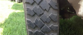
The first reason is that at a speed of more than 70 km per hour, it’s all about the cardan shaft; only the original one must be installed. Next, replace the crosspiece on the cardan shaft, after which you must drag the shaft to a stand and balance it, otherwise the vibration will resume.
The second reason for vibration is the intermediate shaft, it must also be original, otherwise it will quickly fail. We take only the original AvtoVAZ one from the factory, otherwise vibration and breakdowns cannot be avoided.
The third reason for vibration is the breakdown of the gearbox flange bearings. To eliminate the problem, place additional support on the gearbox.
How to overcome noise when maneuvering in a transfer case
You can buy new handles for the levers. We change it ourselves, prying up the support with a screwdriver, take out the lever axis and get rid of the old handles. We remove the old lever springs and install new ones. Insert the lever axis and secure it with a corkscrew nut. Now, when driving with the new handles, there is no characteristic noise in the cabin. The handles can be easily changed without leaving the salon.
Stiff switching of the lock lever
This issue can be easily solved in the following way: when driving, just turn the steering wheel slightly and the lock will immediately turn on without any problems.
There are also: jamming of the pneumatic cylinder, sticking in the neutral position, or the rod is sitting tightly. Burnt gear and shift fork.
Transfer case for Niva, signs of breakdowns:
- problematic engagement of the front axle;
- overheating of the range multiplier;
- leakage or excessive consumption of oil during operation of the transfer case;
- self-switching of the front axle.
Repairing the transfer case in Niva 21213 with your own hands is quite possible in case of minor breakdowns. The owner of a Chevy Niva will only need the basic skills of a car mechanic. It is more difficult to correctly install and center the Niva transfer case. Here it is still recommended to contact a car service. A diagram of the unit itself is presented in the vehicle documentation.
How to replace an outboard bearing
The car is installed on a viewing hole or overpass (you need to turn on first gear and put stops under the wheels to fix it). If the fastening elements are rusty or stuck, you can use
using special means and begin after it has been absorbed and exposed to the bolts and nuts after a short period of time.
Before starting work, it is worth making marks on the cardan, gearbox and box for subsequent correct assembly and avoiding imbalance.
Next, remove the bolts securing the cardan to the rear axle flange and the intermediate support to the frame cross member. The shaft is removed. By the way, when removing the cross, it is also recommended to make marks, marking the position of the forks and shafts. After unscrewing the fastening parts, the outboard bearing is knocked down or pulled out of its seat. If a bearing has been ready to fall apart for a long time, it can usually be removed without much effort. Next, the seat is cleaned and a new part is installed.