Fog lights can be installed on the Priora yourself
Many car owners want to know how to install fog lights on a Priora, because... The climate of our country is predisposed to the periodic occurrence of fogs, especially in the morning and evening. In non-ideal road conditions, the presence of such an accessory will help you better navigate in poor visibility, since the wide beam of standard headlights can “illuminate” a large space, creating a kind of light curtain for both the motorist and oncoming cars.
How to install PTF correctly, and why do you need to replace standard lamps?
Fog lights on Priora, as well as on any other car, are installed quite low, at a level of 0.3-0.7 meters from the road level. In this case, a narrow beam of light enters an area free of wet condensation and actually improves visibility.
But located on the roof of the trunk (additional lighting is often installed on jeeps), they are absolutely useless in a curtain of rain, in fog or during a dust storm. Therefore, fog lights used to be placed under the bumper (for old-style metal structures), but today they are placed directly into it (for modern integrated parts).
Fog lamps must comply not only with traffic regulations, but also comply with UNECE standards. The latter suggest that the fog beam on the Priora and any other car must have a special wide-angle light distribution, with a clearly defined upper limit and dispersion of up to 70 degrees horizontally. Only compliance with these parameters gives the required anti-fog effect.
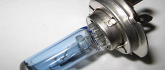
The most common today are fog lights with halogen lamps with a power of 55 watts. They create a luminous flux of 1.1 thousand lumens, which is enough to illuminate a space of 25-30 meters in front of the car.
Replacing conventional incandescent lamps with them is almost always required, because... old-style lamps provide the necessary illumination at a distance of about 8-10 meters, which is clearly not enough for modern driving conditions.
Relays and fuses
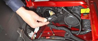
The PTF relay from Priora must be secured with an eyelet under any fastening nut so that the wires do not “dangle” and are not pulled under the hood too much. The relay has four contacts, which are labeled: 85, 86, 30 and 87.
- The 86th contact is connected to the negative side of the battery;
- The 30th contact is connected to the “plus” of the battery;
- The 87th contact is connected to the “plus” of the fog lamp;
- Pin 85 is connected to the button with a blue wire through the PTF fuse on the Priora.
How to choose fog lights?
This is how this headlight shines
Installation of fog lights is preceded by purchasing them at the store. In this case, you must first look at the integrity of the glass of each light bulb, the matching of the headlights and mounting systems.
Compliance with the UNECE is confirmed by the presence of the “E” stamp on the diffuser; it is also desirable to have a GOST terminal, TU, date of manufacture and manufacturer. When we choose fog lights, Priora as a model allows us to purchase articles of predominantly round shape, while the latest fashion is considered to be slit headlights, which have small vertical angles (about 30-50 degrees) and are very well suited as fog equipment.
Fog lights can be produced in:
The first options almost always do not have certification data and have a lot of power, which only causes harm on the road (blinds oncoming drivers). Japanese and European models have moderate power, but are quite expensive. Therefore, when purchasing, it is better to focus on domestic models that comply with GOST standards and are relatively inexpensive.
Installation of anti-fog equipment
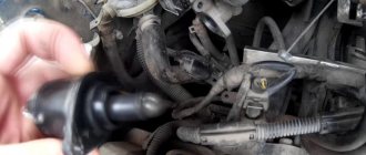
It is impossible to install PTF without dismantling the previous headlight model. For these purposes, the plugs are removed from the bumper, the old headlights are taken out, purchased ones are put in their place and secured with screws. If the size of the holes is not enough for installation, then it is necessary to disconnect the bumper and carry out installation work. If the bumper did not previously have places for fog lights, then they can be made using a sharp knife.
Then you need to lay the wires from the headlights along the cable under the hood in the form of a bundle, which is secured with a clamp. It should be shorter on the left side than on the right. The output of the wires to the control panel is most often installed through the hole behind the fuse box.
The negative wires need to be connected to the car body, after which the crankcase protection (and bumper) is secured in place.
Imported kits often do not include wires, connectors, and plugs, without which it is impossible to install the PTF, so they need to be purchased additionally.
Description of the scheme
The relay must be connected according to this diagram. The relay has only 4 contacts, which are assigned numbers: 85, 86, 87 and 30.
- We connect contact number 86 to the negative of the battery;
- We connect contact number 30 to the “plus” of the battery;
- Contact number 87 is connected to the power wire (plus) of the PTF;
- We connect contact number 85 to the PTF ON/OFF button with a blue wire through a fuse;
Connecting fog lights
Installing a PTF will not take much time if you understand car electrics. Connecting fog lights at the next stage of work assumes that the car owner will independently fix the headlight switches on the front panel of the car. For these purposes, you need to open the decorative panel covering the steering column by turning the locks ninety degrees. Remove the plug, which is located to the left of the clock equipment. Underneath it will be found the wires to which the switch is connected. To connect the fog lights, you need to connect short wires to the contacts of the same name, and carry out the same actions with the heated glass buttons.
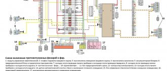
Connection diagram for headlights and other lighting devices
The fog light connection diagram included with the standard equipment kit usually contains detailed information on the headlight installation process, including the possible colors of each wire. Therefore, equipping Priora with this equipment with your own hands is not difficult. To connect the fog lights to the mounting block, you need to mount the “K10” relay, and also install two fuses.
Replacing old or installing new headlights is completed by returning the mounting block to its original location. After which the negative wire can be connected to the battery and checked how the fog lamp connection diagram, which we made ourselves, functions. Note that replacing the PTF using this scheme does not imply an indication of the operation of the headlights on the dashboard.
Connecting Priora foglights
Let's take a closer look at the connection diagram for the Priora fog lights. The fog lights are controlled by the lighting control unit. Specifically, the switches for the front (A5) and rear (A4) fog lights. Upon examination, we can only notice one wire to enable each option. This wire passes through pin 2 to both switches through various resistances because it is a signal wire. It runs from the electrical package control controller to the switch. From the controller side, a stabilized voltage is supplied to this wire. The electrical package control unit controls changes in the amount of current passing through it.
We recommend: Cleaning and adapting the throttle valve on a car
Turn on the rear fog lights.
The rear fog lights of the Priora are turned on as follows. When you press the button on the module (A4), the wire from the electrical package control controller is connected through a negative resistance. In this case, a current of the appropriate magnitude will flow through the circuit, so the controller will receive a signal that this button is pressed. If there is power at pin 14 of block X2 and the low beam headlights are on (see “Prior headlight diagram”), then the processor, through the appropriate key, will supply power to pins 10 and 13 of block X3, to which the rear wiring harness is connected. Voltage will be supplied to the rear fog lamps and to the lighting control module. At the same time, the indicator light on the module will light up.
Turn on the fog lights.
Connecting the Priora fog lights is almost the same. The difference is in the value of resistance, and accordingly in the value of the passing current. Based on the current value, the processor of the lighting control controller determines the position of the front fog lamp button. Therefore, if there is power at pin 12 of the X2 block, the side lights are turned on (see “Prior Dimensions”), power will be supplied to pin 19 of the X2 block.
The green wire with a black stripe will supply voltage to the coil of the K10 electromagnetic relay. The coil armature will be attracted and close the contacts. In this case, fuses F17 and F18 with a nominal value of 10A will receive power, and from them, through the connecting connector of the instrument panel harness and the front harness, the lamps in the fog lights will receive power. In addition, the LED on the lighting control module will receive power from fuse F17, signaling that the headlights are on.
When you press both power buttons simultaneously, the current value will also change. Since in a parallel connection the total resistance is always less than the smaller one. That is, the value of the passing current will be maximum. Connecting Priora foglights according to this scheme makes troubleshooting very difficult, without the presence of diagnostic equipment for the electrical package control controller. If malfunctions occur, it is necessary to check the integrity of fuses, relays, operation of side lights and low beam headlights.
Adjusting the luminous flux from PTF
A car enthusiast needs to know not only how to install and connect fog lights, but also how to adjust their luminous flux. To do this, you need to check the tire pressure, load the car with cargo close in weight to the total weight of the passengers, fill the tank with gasoline, and put on a spare tire.
Then the car (Priora se or another modification) is placed on a flat area opposite a steep smooth wall at a distance of five meters, and the fogs are turned on. Next, the distance from the center of the headlights to the ground is measured, and a line is drawn on the wall five centimeters lower than this distance. After this, you need to adjust the light spot so that its upper boundary is at the level of the drawn line.
The work is carried out for each headlight separately (with one of the headlights closed), after which the results are compared, and the position of the light spots is replaced until both are at the same level. Domestic-made headlights are adjustable only in the “up” and “down” positions; all work with them is done using a long or Phillips screwdriver.
Check and adjust the headlights on a equipped Lada Priora VAZ 2170 car: with a fully filled fuel tank, a set of tools and a spare wheel.
To adjust the headlights on a Lada Priora VAZ 2170, you will need a “6” hexagon. 1. Pre-check and, if necessary, adjust the tire pressure to normal. 2. Place the car perpendicular to a smooth wall (for example, a garage) at a distance of 5 m. Place an additional weight weighing 75 kg on the driver’s seat. Mark the screen on the wall as shown in Fig. 4.4, and draw vertical lines on it: center line O and lines A, B, passing through the points corresponding to the centers of the low beam headlights. These lines must be symmetrical with respect to the center line of the vehicle. At a height h corresponding to the distance of the centers of the headlights from the floor, draw line 1 and 75 mm below it, line 2 of the centers of the light spots. 3. Turn on the ignition and low beam headlights, turn the headlight adjustment knob to position “0” (this position corresponds to the load of a car with one driver). Screws 1 (in the vertical plane) and 2 (in the horizontal plane) manually adjust the light beam to position the light spot for each headlight on the screen, if the location of the light spots on the screen does not correspond to the picture. 5. Adjust the direction of the light spot for each headlight separately. During adjustment, cover the second headlight with opaque material or disconnect the wire connector from it. 6. The headlights are considered adjusted if the upper border of the left parts of the light spots coincides with line 2, and the vertical lines A and B pass through the intersection points of the horizontal and inclined sections of the light spots.
Adjusting the fog lights
Select a flat horizontal area at a distance of five meters from the screen. Any flat vertical surface, such as a wall, garage door, etc., can serve as a screen.
— Check the tire pressure.
Lighting repair
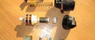
In some cases, owners need to disassemble and repair the headlight due to a malfunction of its components, to replace glass, with regular formation of condensation, or for tuning:
- We dismantle the lantern.
- The headlight unit consists of two parts connected with glue or sealant. Use a hairdryer to heat the joint around the circumference until the glue becomes softer.
- Separate the glued parts from each other with a screwdriver, cutting the glue with a mounting knife and continuing heating. On BOSCH headlights, remove the four latches.
- We clean the disassembled parts from glue with a mounting knife and sandpaper.
- Upon completion of the repair, glue the separated parts together with sealant.
Then you need to wrap the headlight with plastic film and tape and leave until the sealant polymerizes.
Headlight adjustment
The headlights are adjusted according to the diagram (it needs to be placed on a wall, for example, in a garage):
- We draw a horizontal line 1 on the screen at a height equal to the distance from the center of the headlights to the floor.
- Below it, 65 mm, draw a parallel line 2.
- We draw on the screen a vertical center line 0 (the distance from it to the center of the left and right headlights should be equal) and lines corresponding to the centers of the headlights (AE and BE).
The vehicle must be in running order (fully fueled and without additional cargo). Check tire pressure.
Checking the direction of headlight beams
:
- Place the car on a flat horizontal platform at a distance of 5 meters from the screen.
- Place a 75 kg weight on the driver's seat or have an assistant sit on the seat.
- Set the headlight range control switch to position “O”
- Cover the light of one headlight with thick material.
- Turn on the low beam headlights and check the location of the light spots on the wall.
- The upper boundary of the light beam should coincide with the lower horizontal line, and the point where the beam breaks (the point of intersection of the horizontal and inclined sections of the light flux) should coincide with the vertical line corresponding to the center of the headlight.
Adjusting the headlights (hexagon “6”)
:
- Regulator No. 1 (located closer to the axis of the car) changes the position of the headlight beam in the vertical plane.
- Regulator No. 2 (located closer to the car fender) changes the position of the light beam in the horizontal plane.
- We turn the adjusters with a hexagon until the headlights are adjusted.
The video shows an example of how to adjust Priora headlights manually in the field:
PTF adjustment
Draw a horizontal line on the screen 50mm lower than the height from the fog lights to the ground. The light spot should be positioned so that the upper border on the screen is at the level of the drawn strip. The adjustment is made by rotating the adjusting screw, which is located next to the fog lamp.
Let us remind you that we previously told you how to independently replace the lamps in the Priora headlights, as well as install PTF.