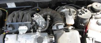
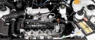
The VAZ-2115 has a gasoline engine, four-cylinder, in-line, four-stroke, with an overhead camshaft, eight-valve. The cylinders operate according to the following scheme: 1–3–4–2, counting from the crankshaft pulley. The system is powered through electrically controlled distributed fuel injection.
Fig.1 VAZ 2115 car engine
- coolant supply pipe;
- engine cylinder complex;
- thermostat;
- coolant temperature sensor;
- outlet pipe;
- engine cylinder head plug;
- engine cylinder head cover;
- fuel pressure level regulator;
- oil filler cap;
- throttle cable;
- throttle assembly;
- idle air control;
- throttle position sensor;
- receiver;
- rear cover of the gas distributor drive;
- front cover of the gas distributor drive;
- injector;
- fuel rail fitting plug;
- fuel ramp;
- intake manifold;
- right intake manifold support bracket;
- generator drive pulley;
- Oil filter;
- crankshaft position sensor;
- oil pan;
- intake manifold;
- connecting rod;
- crankshaft;
- intake manifold support bracket left;
- flywheel.
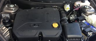
The engine, together with the clutch and gearbox, form a power unit in the engine compartment - a block on three rubber-metal supports.
The cylinder block is made of cast iron. The nominal diameter is 82 mm, it can be increased by 0.4 or 0.8 mm during repairs. The cylinder class marking is marked on the bottom plane in Latin letters according to the cylinder diameter in millimeters. The permissible level of cylinder wear is 0.15 mm per diameter.
The cylinder block contains five bearing supports, which are bolted to the block. The covers are not interchangeable, since the holes for the bearings are modified in the assembly with the covers. To distinguish them, they are marked on the outside with marks. Thrust half-rings in the middle support prevent axial displacement of the crankshaft.
There is a steel-aluminum half-ring installed in the middle, and a yellow metal-ceramic one at the back. In this case, their grooves face the crankshaft. If the crankshaft play exceeds 0.35 mm, the half rings should be replaced.
Thin-walled shells for connecting rod and main bearings are made of steel-aluminium. The main upper bearings of the first, second, fourth and fifth supports have a groove on the inner surface. The lower main bearing and the upper bearing of the third bearing are without grooves, just like the connecting rod bearings.
The crankshaft is made of high strength cast iron and has journals: main and connecting rod. The shaft has eight counterweights cast with the shaft. Oil is supplied from the main crankpins to the connecting rod journals through drilled channels. The channel entrances to the shaft cheeks are closed with plugs. The channels also serve for oil purification: the rotation of the crankshaft throws resins and solid particles towards the plugs under the influence of centrifugal forces. When dismantling the crankshaft, it is advisable, and before balancing it is simply necessary, to clean these channels from accumulated deposits. The plugs cannot be reused.
The camshaft drive pulley is keyed on the crankshaft at the front end. The generator drive pulley is also attached to it, which serves as a shaft vibration damper.
The flywheel is attached to the rear end of the shaft through a washer with six bolts. The flywheel is cast from cast iron and has a steel toothed ring, which serves as the engine starter.
The connecting rods are made of steel. Their cross-section is an I-beam. The connecting rods are processed together with the covers. In order not to be confused during assembly, the cylinder number is stamped on the covers. A steel-bronze bushing is pressed into the upper head of the connecting rod.
The piston pin is made of steel, tubular in cross-section. The finger rotates freely on the bosses (floating type) and is secured with locking spring rings to prevent it from falling out. They are located in grooves on the piston bosses.
The piston is made of aluminum alloy. The piston skirt has a complex shape: conical in longitudinal section and oval in cross section. Three grooves are machined for the piston rings in the upper part of the piston. There are drillings in the oil ring groove that also serve to supply oil to the piston pin. The hole under the piston pin is offset by 1 mm from the diametrical plane; when installing the piston, you need to orient yourself along the arrow on its bottom: the direction towards the shaft pulley.
In order to reduce imbalance, engine pistons in the crank mechanism are selected based on mass: the spread should be no more than 5 g.
The piston rings are located in the grooves of the piston. The upper rings are compression. These rings prevent gas from escaping into the crankcase and provide heat transfer to the cylinder from the piston. The lower ring is an oil scraper ring. The oil collected from the cylinder walls is transferred to the holes in the piston bosses and lubricates the piston pin.
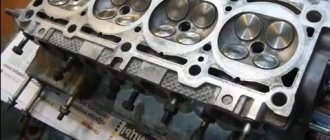
The cylinder head is made of aluminum alloy and is common to all cylinders. It is centered on two bushings. Fastening to the block is carried out with ten screws. A metal-reinforced non-shrink gasket is installed between the head and the block. Its reuse is not permitted.
There are five supports located at the top of the cylinder head. The camshaft supports are detachable, and their holes are machined in assembly with the front and rear bearing housings.
The camshaft is made of cast iron. The design of the shaft is five-bearing. The camshaft is driven into rotation from the crankshaft by a toothed belt. There are marks on the toothed pulleys for proper installation. If the mark of the crankshaft pulley corresponds to the mark of the oil pump housing, then the mark of the camshaft pulley corresponds to the bent antenna of the rear cover of the gas distributor drive.
The guide bushings and valve seats are pressed into the cylinder head. The holes in the bushings are finalized after pressing. Grooves for lubrication are cut on the inner surface of the bushings: along the entire length of the intake valves, and up to half the length of the exhaust valves. Oil reflective caps placed on the bushings are made of oil-resistant rubber.
The valves are made of steel. The exhaust valves have heads made of heat-resistant steel. They are arranged in a row, at an angle to the plane in which the cylinder axes lie. The exhaust valve plate is narrower than the intake valve. The washers that regulate the valve clearance are made of 20X steel. In order to increase their wear resistance, the surface is pre-nitrocemented.
The pushers are made in the form of cylindrical cups; they move in the holes of the cylinder head and rest on the ends of the valves. In order to increase wear resistance, the surface that comes into contact with the valve is carburized. The rotation of the pushers during engine operation is carried out by shifting the cam axis from the pusher axis by 1 mm.
The valve closes under the action of springs. They rest with their lower ends on the washer, and the upper plate is held in place by breadcrumbs. Their shape is a truncated cone, and the inner surface is resistant flanges that fit into the grooves on the valve stem.
Combined engine lubrication is used: the connecting rod and main bearings and the camshaft journal-support pairs are lubricated under pressure; splashing of oil onto the cylinder walls (and further to the pins and piston rings), in the pushrod-camshaft cam pair and to the valve stems. The remaining components are lubricated by gravity.
The oil pump in the VAZ-2115 car engine is gear-type, with a pressure reducing valve, internal gearing. The pump is mounted in a housing attached to the cylinder block. The drive gear (smaller) is mounted on two shaft flats at the front end.
The oil receiver is bolted to the pump housing and the bearing cover (second main). The oil filter is non-separable, full-flow, with anti-drainage and bypass valves.
Crankcase ventilation is a closed circuit, with forced removal of gas through an oil separator.
For an overview of the engine characteristics of the VAZ-2115 car, watch the video:
Engine 1.6 l 16-valve (16-cl.)
Engine 1.6 l 16-cl.
On VAZ-2114, 2113, 2115 in a limited series from the SuperAvto production, engines from Dvenashka and Priora were installed.
Engine 21124 1.6 l 16-cl:
- Power - 89 hp. With.
- Torque - 131 Nm at 3100 rpm.
- Acceleration to 100 km/h - 11.5 s.
Engine 21126 1.6 l 16-cl:
- Power - 98 l. With.
- Torque - 145 Nm at 4000 rpm.
- Acceleration to 100 km/h - 10.5 s.
Malfunctions
| FAULTS | CAUSES AND REMEDIES |
| The engine does not start or runs with detonation and strong vibrations. | Injection system failure. It is necessary to open the engine, clean the injectors and check their functionality. |
| The engine is shaking, the idle speed is floating. | The throttle sensor or idle speed control has failed. Repairs are made only after a thorough diagnosis and consist of replacing the failed element. |
| The engine takes a long time to warm up or does not reach operating temperature at all. | The thermostat failed, which closed the circulation of liquid along a large circuit. The repair consists of replacing the thermostat. |
| The appearance of an extraneous knocking sound in the engine under load. | Valves are knocking and require adjustment. Repair in this case involves opening the engine and adjusting the valve clearance. |
Which engine is better: 1.5 liter 8-cl. or 1.6 l 8-cl?
When choosing a car, people often ask the question: “Which engine is better?” In our case, everything is not so simple. A similar question may arise if we consider buying a car from already “shaggy” years: 2006-2007. It was during this period that VAZ-2113, 2114 and 2115 were equipped with both 1.6 liter and 1.5 liter engines, the characteristics of which are outlined above.
In fact, they are no different, except for volume, exhaust standards, fuel supply systems and a pair of sensors. Therefore, the main distinguishing point is the engine size. A difference of 0.1 liters gives more torque from the bottom, adds a little maximum power and, perhaps, the same or even lower fuel consumption than 1.5 liters. The only negative is that it is noisier at idle.
Previously, in the years 2008-2012, people were reluctant to buy 1.6 liter models, saying they were loud, prone to breakdowns, etc. In fact, it is superior to the 1.5 liter engine in all respects. Accordingly, we recommend it to you. But this applies to 8-grade students. motors that were installed serially. Next, let's look at 16-cl.
Maintenance
This power unit is not demanding on service, so the oil in the VAZ 2115 engine is changed every 15 thousand kilometers, and it is possible to use inexpensive semi-synthetic and mineral oil.
We only note the need to replace the timing belt, which is done every 50 thousand kilometers.
One of the serious shortcomings is the lack of hydraulic compensators, which forces the car owner to adjust the valve clearance manually every 10 thousand kilometers.
To perform this service work, the valve cover must be removed and the clearances measured and adjusted. This is quite a complex service job and it is difficult to do it yourself.
Which engine is better, 1.6 16- or 8-valve?
16 classes the engines were installed in a limited series at AvtoVAZ or at the SuperAvto subsidiary. They were also installed by tuning fans themselves.
In terms of manufacturability, they are superior to 8-cl. engines. Accordingly, if there is an option to take a 16-cl. motor, it would be nice to go with this option. But everything has its own nuances.
Advantages of 16-valve engines over 8-valve engines
- The best cylinder blowing is more power.
- More stable engine operation - less noise.
- Greater efficiency means lower fuel consumption.
However, 16th grade. the engine (1.6 l) from Priora (21126) bends the valves when the belt breaks. For some reason this scares many people. You just need to monitor the condition of the car, belts, rollers, pump, then everything will be fine! On all modern cars the valves bend.
Tuning
There are several possible ways to increase engine power. Let's talk about these tuning options in more detail:
- Chip tuning of the VAZ 2115 engine will not allow you to obtain any noticeable effect. Even by replacing the engine control unit, the car owner will be able to get 3-5 horsepower, the increase of which will be almost imperceptible.
- Deep engineering tuning of VAZ 2115 engines, which involves replacing the camshaft and other power elements, will increase the engine power to 85 horsepower. Such an increase of 10 horses will already be noticeable, and the car will accelerate faster, especially from low revs.
- Replacing the throttle body and exhaust will increase power to 95 horsepower.
- If the engine power limit of 100 horses is important to you, then you need to install lightweight valves, mill the cylinder head and replace the intake manifold. A car with such a tuned engine will accelerate 1-2 seconds faster than with a basic 78-horsepower engine. A further increase in power by replacing internal power parts will not allow you to obtain the desired horsepower, and the service life of the motor is significantly reduced.
- An alternative way to increase the power of a VAZ 2115 engine is to install a compressor with a pressure of about 0.5 bar. If the compressor is properly configured, the engine power will be about 120 horsepower. At the same time, when resorting to such tuning, the car owner must be prepared to reduce the service life of the engine, which may require appropriate major repairs after only 75-100 thousand kilometers.
Interior
The interior decoration is simple, with regular chairs with fabric upholstery. In the back there is a sofa for three passengers. There is not much space, but in principle it is enough. There is a simple stove, which is very easy to operate, since everyone is familiar with this unit.
The steering column is familiar to many - a simple 3-spoke steering wheel. The instrument panel is also made in the classic style for AvtoVAZ, these are ordinary analog gauges and a small and uninformative on-board computer.
The trunk of the car, of course, is not particularly large, but for ordinary purposes it is enough. The luggage compartment volume is 445 liters.
In principle, the VAZ 2115 is an acceptable car for its price; of course, it has disadvantages and problems, but the price tells you about it.
What does the VAZ-2115 engine consist of?
The VAZ-2115 has a gasoline engine, four-cylinder, in-line, four-stroke, with an overhead camshaft, eight-valve. The cylinders operate according to the following scheme: 1–3–4–2, counting from the crankshaft pulley. The system is powered through electrically controlled distributed fuel injection.
Fig.1 VAZ 2115 car engine
- coolant supply pipe;
- engine cylinder complex;
- thermostat;
- coolant temperature sensor;
- outlet pipe;
- engine cylinder head plug;
- engine cylinder head cover;
- fuel pressure level regulator;
- oil filler cap;
- throttle cable;
- throttle assembly;
- idle air control;
- throttle position sensor;
- receiver;
- rear cover of the gas distributor drive;
- front cover of the gas distributor drive;
- injector;
- fuel rail fitting plug;
- fuel ramp;
- intake manifold;
- right intake manifold support bracket;
- generator drive pulley;
- Oil filter;
- crankshaft position sensor;
- oil pan;
- intake manifold;
- connecting rod;
- crankshaft;
- intake manifold support bracket left;
- flywheel.
The engine, together with the clutch and gearbox, form a power unit in the engine compartment - a block on three rubber-metal supports.
The cylinder block is made of cast iron. The nominal diameter is 82 mm, it can be increased by 0.4 or 0.8 mm during repairs. The cylinder class marking is marked on the bottom plane in Latin letters according to the cylinder diameter in millimeters. The permissible level of cylinder wear is 0.15 mm per diameter.
The cylinder block contains five bearing supports, which are bolted to the block. The covers are not interchangeable, since the holes for the bearings are modified in the assembly with the covers. To distinguish them, they are marked on the outside with marks. Thrust half-rings in the middle support prevent axial displacement of the crankshaft.
There is a steel-aluminum half-ring installed in the middle, and a yellow metal-ceramic one at the back. In this case, their grooves face the crankshaft. If the crankshaft play exceeds 0.35 mm, the half rings should be replaced.
Thin-walled shells for connecting rod and main bearings are made of steel-aluminium. The main upper bearings of the first, second, fourth and fifth supports have a groove on the inner surface. The lower main bearing and the upper bearing of the third bearing are without grooves, just like the connecting rod bearings.
The crankshaft is made of high strength cast iron and has journals: main and connecting rod. The shaft has eight counterweights cast with the shaft. Oil is supplied from the main crankpins to the connecting rod journals through drilled channels. The channel entrances to the shaft cheeks are closed with plugs. The channels also serve for oil purification: the rotation of the crankshaft throws resins and solid particles towards the plugs under the influence of centrifugal forces. When dismantling the crankshaft, it is advisable, and before balancing it is simply necessary, to clean these channels from accumulated deposits. The plugs cannot be reused.
The camshaft drive pulley is keyed on the crankshaft at the front end. The generator drive pulley is also attached to it, which serves as a shaft vibration damper.
The flywheel is attached to the rear end of the shaft through a washer with six bolts. The flywheel is cast from cast iron and has a steel toothed ring, which serves as the engine starter.
The connecting rods are made of steel. Their cross-section is an I-beam. The connecting rods are processed together with the covers. In order not to be confused during assembly, the cylinder number is stamped on the covers. A steel-bronze bushing is pressed into the upper head of the connecting rod.
The piston pin is made of steel, tubular in cross-section. The finger rotates freely on the bosses (floating type) and is secured with locking spring rings to prevent it from falling out. They are located in grooves on the piston bosses.
The piston is made of aluminum alloy. The piston skirt has a complex shape: conical in longitudinal section and oval in cross section. Three grooves are machined for the piston rings in the upper part of the piston. There are drillings in the oil ring groove that also serve to supply oil to the piston pin. The hole under the piston pin is offset by 1 mm from the diametrical plane; when installing the piston, you need to orient yourself along the arrow on its bottom: the direction towards the shaft pulley.
In order to reduce imbalance, engine pistons in the crank mechanism are selected based on mass: the spread should be no more than 5 g.
The piston rings are located in the grooves of the piston. The upper rings are compression. These rings prevent gas from escaping into the crankcase and provide heat transfer to the cylinder from the piston. The lower ring is an oil scraper ring. The oil collected from the cylinder walls is transferred to the holes in the piston bosses and lubricates the piston pin.
The cylinder head is made of aluminum alloy and is common to all cylinders. It is centered on two bushings. Fastening to the block is carried out with ten screws. A metal-reinforced non-shrink gasket is installed between the head and the block. Its reuse is not permitted.
There are five supports located at the top of the cylinder head. The camshaft supports are detachable, and their holes are machined in assembly with the front and rear bearing housings.
The camshaft is made of cast iron. The design of the shaft is five-bearing. The camshaft is driven into rotation from the crankshaft by a toothed belt. There are marks on the toothed pulleys for proper installation. If the mark of the crankshaft pulley corresponds to the mark of the oil pump housing, then the mark of the camshaft pulley corresponds to the bent antenna of the rear cover of the gas distributor drive.
The guide bushings and valve seats are pressed into the cylinder head. The holes in the bushings are finalized after pressing. Grooves for lubrication are cut on the inner surface of the bushings: along the entire length of the intake valves, and up to half the length of the exhaust valves. Oil reflective caps placed on the bushings are made of oil-resistant rubber.
The valves are made of steel. The exhaust valves have heads made of heat-resistant steel. They are arranged in a row, at an angle to the plane in which the cylinder axes lie. The exhaust valve plate is narrower than the intake valve. The washers that regulate the valve clearance are made of 20X steel. In order to increase their wear resistance, the surface is pre-nitrocemented.
The pushers are made in the form of cylindrical cups; they move in the holes of the cylinder head and rest on the ends of the valves. In order to increase wear resistance, the surface that comes into contact with the valve is carburized. The rotation of the pushers during engine operation is carried out by shifting the cam axis from the pusher axis by 1 mm.
The valve closes under the action of springs. They rest with their lower ends on the washer, and the upper plate is held in place by breadcrumbs. Their shape is a truncated cone, and the inner surface is resistant flanges that fit into the grooves on the valve stem.
Combined engine lubrication is used: the connecting rod and main bearings and the camshaft journal-support pairs are lubricated under pressure; splashing of oil onto the cylinder walls (and further to the pins and piston rings), in the pushrod-camshaft cam pair and to the valve stems. The remaining components are lubricated by gravity.
The oil pump in the VAZ-2115 car engine is gear-type, with a pressure reducing valve, internal gearing. The pump is mounted in a housing attached to the cylinder block. The drive gear (smaller) is mounted on two shaft flats at the front end.
The oil receiver is bolted to the pump housing and the bearing cover (second main). The oil filter is non-separable, full-flow, with anti-drainage and bypass valves.
Crankcase ventilation is a closed circuit, with forced removal of gas through an oil separator.
For an overview of the engine characteristics of the VAZ-2115 car, watch the video:
www.vsepoedem.com
Differences between the model and its predecessors
It is worth noting that this car has undergone the most significant changes in comparison with previous representatives of the line. The car body was completely modernized: it acquired smoother contours and became 22 centimeters longer.
The front of the car acquired original narrow headlights, the shape of the hood and front fenders changed. The bumpers took on modern shapes and began to be painted in body color, and additional brake lights appeared on the rear spoiler. The rear lights were supplemented with intermediate inserts, which increased the attractiveness of the rear of the car.
The trunk volume and carrying capacity of the vehicle have increased. The interior of the car has also changed, which is complemented by an updated dashboard and improved seats. The built-in steering column adjuster lever, which made it possible to set the optimal position of the steering wheel for drivers of different builds, also speaks in favor of the model.