Sometimes motorists may express a desire to balance the crankshaft themselves. At home, such a procedure may be especially necessary for those who want to independently recognize their car or do not trust its repair and maintenance to service center specialists. In fact, balancing crankshafts is a mechanical operation that should reduce vibration and other types of loads on the elements of the power unit. By balancing, you can increase the reliability, operability and even performance of the engine.
Why is crankshaft balancing necessary?
Balancing crankshafts is nothing more than a mechanical operation, as a result of which vibrations and other types of loads on engine elements are significantly reduced. This allows you to increase its reliability, operability and productivity. Of course, most often such an operation requires already worn-out mechanisms, although there are cases when an imbalance is observed in a brand new car, just purchased from the showroom.
You can understand that you are about to balance the crankshaft yourself, and it’s time to roll up your sleeves, by the following signs. First of all, pay attention to the gear shift knob when idling, it begins to dangle. The engine itself will behave in the same way, so don’t forget to look under the hood of your “iron horse”.
As for the reasons for this behavior, there may be several of them. Among them, it is impossible to exclude possible errors made during the manufacture of mating parts. In addition, the heterogeneity of the materials from which the crankshaft elements are made does not have the best effect. The appearance of backlash is also facilitated by increased gaps in the mating units, their misalignment, poor-quality installation and, of course, insufficiently accurate centering.
And don’t forget about natural wear and tear, which has never played a positive role.
Down with the vibration. Balancing the HF and flywheel in the garage.
Everyone who has encountered a boxer engine knows about its hellish vibration, some have more, others have less, which brings its own huge disadvantages to the operation of the engine. Constant loosening of screws and nuts, looseness at idle, inability to spin the engine, ignition failures, etc.. Due to the impossibility of balancing the HF anywhere in any office, after racking my brains and surfing the Internet, I came across this video - https ://www.youtube.com/watch?v=tnhVK1mInLQ&list=UUorynE2CPqF5NB_sBpCgxSQ... therefore, do not accuse him of plagiarism. Having carried out this entire operation with my engine, I decided to describe it in more detail. I fitted the electric motor, 1280 rpm, first made a plastic pulley, but then abandoned it, putting the belt directly on the knee (the electric motor was spinning constantly, the belt slipped on the knee, heating it, but not much. This is the main reason for the failure from the pulley on the HF (saving time on on and off)).
At first I spun it with the flywheel installed, the shift of weight caused the engine to throw like an airplane in a turbulence zone, it didn’t want to spin up, the electric motor. there was simply not enough power, such a huge difference (and we want to create a twisting motor, gee-gee), half a day of shamanic dances and zero results, the desire to melt it in a forge and drown the ingot in a pond. The mistake was that I tried to hang it up right away, but that was not the case. I removed the flywheel and discovered that there was an even larger crossbar on the knee; I had to hold it with both hands; the crankcase was mercilessly nailed to the floor.
Having rummaged around in a heap of all sorts of junk from repairing everything, I found a belt tensioner pulley from my Volga, heated the inner hole with a gas burner and put it on a cone, not too much, the flywheel bolt caught with only 2-3 turns, drilled holes in a circle and cut threads dia. 8mm and 6mm (screwdriver with tap works). I took bolts of different lengths. I take the largest one, screw it into the roller, put a mark with chalk, spin the HF to the maximum (until the electric motor starts to go out), stop the HF, move the bolt 90 degrees, unwind again, etc.. I mark the sectors with the least vibration, and already I search them, find the minimum vibration value (and the engine jumps), add or reduce weight until I find the minimum. I found it (the engine still jumps, don’t pay attention), on the contrary I drill a hole in the counterweight, approximately like bolts by eye. I put a mark on the video where the load was for further analysis. I'm spinning it, OPANKA, it's better. Again the bolt, sectors, marks, weight, drill. Bolt, sectors, marks, weight, drilling. And so the day. The HF began to spin up gently, there was a pleasant rustling of the bearings, acceleration, HZ, probably about ten thousand it accelerated just like the HF, the vibration was very small and soft, I couldn’t hang it up, either with large or small weights, and it wasn’t necessary, it was even pleasant. I’m tired, my back hurts, I’m thinking about the flywheel for tomorrow, I decided to install it anyway and try it. I put it on, spin it up and... YOPT. SILENCE. A mosquito produces more vibration. And the flywheel was lightened by Uncle Vasya, a groove for the belt, I thought it was an imbalance, an imbalance, but this is how it turned out. And this is what the knee looks like. Now the engine will spin much easier and more fun and the speed bar will also rise (analyzing the behavior of the electric motor before and after). All that remains is to drill out the intermediate clutch discs, check them, and that’s it. Respect to the guy for the idea!!! I’ll add: in the HF, before balancing, unscrew the plugs, clean, rinse, blow out the channels, return the plugs to the original ones. I can make a video of the promoted engine, it stands rooted to the spot. And for comparison, I have another knee.
Where to balance the crankshaft - repair options
There are two ways to balance the crankshaft. The first is static, it is less accurate. In this case, special knives are used, on which the part is installed. And the imbalance is determined by its position during rotation. If the upper part of the crankshaft is lighter than the lower part, then weights are attached to it and such measurements and additional loading are made until balance is achieved. And only after that, holes for the counterweight are drilled on the opposite side.
The second type is dynamic balancing of the crankshaft. To carry it out, special equipment is required. The crankshaft is installed in floating beds and spun to the required speed. The light beam finds and scans the heaviest point that provokes shaking, and displays it on the screen. And to achieve balance, the only thing left to do is remove excess weight from it.
Types of crankshaft balancing
Currently, two main types of balancing are used:
- Dynamic , providing high accuracy and requiring the use of special machines.
- Static . This type of balancing is used for parts made in the shape of a disk and having the following ratio of diameter (D) and length (L): D>L.
Balancing a crankshaft that has an asymmetrical (for example, V-shaped) design or an odd number of cylinders has certain features, since the momentary component of such shafts is quite high and can tear it off the mounting supports.
This can be avoided by installing compensator bushings with a weight adjusted to one gram on the connecting rod journals. If these parameters are not available in special sections of the technical and operational documentation of the power unit, they are calculated discretely. There are individual methods for this.
The next point that requires a fairly clear understanding is the identification of cases that necessitate balancing the crankshaft:
- Installing non-standard or performing facilitating measures on standard connecting rod and piston groups.
- Carrying out work on straightening deformed crankshafts.
- Replacing the flywheel. It should be noted here that in this case dynamic balancing is not always necessary. In some cases, it is sufficient to perform only static balancing.
So, we consider it established that balancing non-mirror symmetrical crankshafts, a special case of which is the V-shaped crankshaft, requires the use of compensating bushings (often made to special order), creating an imitation of a dynamic effect similar to that of connecting rod-piston groups.
Which engines use balancer shafts?
The Japanese company Mitsubishi was the first to use balancer shafts in 1976. The new product is called “Silent Shaft”, which means “silent shaft”.
They are mainly installed on four-cylinder engines with a volume of more than two liters and with an in-line arrangement of cylinders, since it is this design that is most susceptible to vibration and noise.
Balancer shafts are also often used on powerful diesel engines. Now they can be found not only on Japanese models, but also on European and American ones.
What are balancers used for?
The main task of balancing shafts is to absorb excess inertia and reduce vibration. This became relevant after the advent of more powerful engines with a volume of two liters or more.
Balancer shaft block with gear drive from the engine crankshaft
The location of the cylinders also plays a significant role in the balance of the internal combustion engine. There are three common schemes:
- Arrangement in a row, when the cylinders are located in the same plane.
- Opposed scheme, when the axes of the cylinders are in the same plane and oppositely directed to each other.
- V-shaped arrangement of cylinders.
The location of the cylinder axes directly affects engine balancing. The in-line design has proven itself well in small-volume 4-cylinder engines. The opposite circuit gives the best balancing performance. The V-shape requires precise angles between the cylinders to achieve optimal balance.
Be that as it may, ideal balance cannot be achieved in any circuit, which is why balancers are installed.
How to use?
Using a carriage puller to remove it is quite simple:
- remove the connecting rods using a connecting rod puller;
- if the carriage is square, then it is better to start on the left side;
- match the splines of the puller with the splines on your carriage;
- if the puller has a centering axis, screw it into the carriage shaft;
- Unscrew the carriage cup, then repeat the same steps on the other side.
Remember that most carriages have right-hand threads on the right and left-hand threads on the left. With the exception of Italians, where both cups have right-hand threads. Different companies have different tools. You may need an additional wrench to turn the carriage puller itself, or your puller may already have a handle. However, there are no very difficult or incomprehensible moments in using the puller, and anyone can figure it out.
Drive types
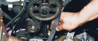
Since balancing shafts are designed to balance the crankshaft, their operation must be synchronized with this part of the unit. For this reason, they are connected to the timing drive.
To dampen rotational vibrations, the drive gear of the balancer shafts has springs. They allow the drive to rotate slightly around its axis, ensuring a smooth start to movement of the device.
Most often, a common drive belt or chain is used, mounted on the motor. Gear type drives are much less common. There are also combined modifications. In them, the shafts are driven by both a toothed belt and a gearbox.
Balancing the crankshaft of Chinese bicycle engines
The price of the textbook is 45 kopecks. O. K Dedushkin, O. G Vagner
Moped science 3rd grade
Balancing the crankshaft of Chinese bicycle engines.
Third edition, expanded, with illustrations
Chapter 1: Getting data for balancing.
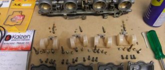
To carry out operations to balance the crankshaft of a Chinese engine (hereinafter referred to as CM), we need to remove the crankshaft itself and its attachment in the form of a magnet and a centrifugal clutch (or without it) from the engine.
We went through the removal of crankshafts in second grade, I think everyone remembers this material. I see that Rzhevsky remembers.
Also (the teacher continued in a boring voice)
You and I will need a piston with attachments in the form of rings, stoppers, a needle bearing and a pin.
It is not at all necessary to disassemble the piston into atoms. Artyomka, don’t turn around, you’re preventing Pavel from learning his lesson.
We weigh the connecting rod head. To do this, we balance the scales with torn newspapers. Nobody giggles, otherwise I’ll kick you out of class.
After that, we place the connecting rod head on one bowl, and install weights on the second bowl so that the head
(Rzhevsky, out of class)
of the connecting rod rises to a horizontal position.
Bring water to Rzhevsky, he has developed epilepsy.
And pick him up off the floor. After weighing the connecting rod head, it is necessary to weigh the piston with the attachment. Now we have the data to make calculations.
Let's take a balancing factor of 0.6. Don’t ask me what this number is, this is studied in high school mathematics, after the limits of increments and additions of matrices. You can read in Ierusalimsky’s book “The Theory of Motorcycle Calculations”
So, the formula:
( m piston with attachment +
m connecting rod head)*0.6 – m connecting rod head = m balancing weight
The balancing weight is hung on the connecting rod head. It is convenient to make a weight in the form of a bolt with a nut. To accurately select the weight, washers and plasticine are used.
Ideally, after hanging the load, the crankshaft on the bearings should occupy a position of static equilibrium. That is, take an arbitrary position and not try to turn anywhere.
In our case, the crankshaft turns sharply with the connecting rod down. For balance you need more than 28 grams. It is convenient to use counterweights in the form of magnets; you can use plasticine. Counterweights are needed to determine a very approximate mass for adjusting the weight of the crankshaft cheeks.
In fact, the mass may be greater. But for a first approximation, the data obtained is quite sufficient.
(Everyone became quiet: “I wish it was like that right away, Grandfather always tells important things. Anyone who hears will know Zen.”)
Chapter 2: Operations to compensate for the weight of a complexly balanced system with vertical and horizontal components.
The crankshaft will have to be disassembled. Each cheek pad is secured with three screws, the screws are reinforced with epoxy resin. Therefore, each screw must be heated with a soldering iron or heat gun before unscrewing. Without fanaticism, gas burners and blowtorches. Be sure to note the position of the linings relative to the crankshaft, what and how they were installed. To then screw it to the same place in the same position.
Interestingly, traces of balancing are present. But this is balancing for the lighter KD-50 piston. How else can you explain that the compensation weight is tied to the difference in the weight of the pistons? (KD50 - 70 grams, KD 80 - 120 grams) The assumption of one universal crankshaft for five abstract motors is confirmed.
First, let's define what drilling gives. We drill five holes to half the depth of the remaining thickness of the lining - this is only a measly 4 grams. And we need about a third more than 28.5:2, because we have two overlays.
We drill holes through. The material of the linings resembles cast iron and crumbles into fine dust. Therefore, the partitions must be preserved. Using a cutter all over is not an option. It’s more interesting here, more than 15 grams.
Now, for the sake of dynamic balance, the weight of the cheeks must be equalized. This can be solved by filing, chamfering, and so on. The exact weight of the pad is not important at this stage.
The weight is finally selected after assembling the crankshaft. The screws are also secured with epoxy, after which the crankshaft is drilled through the holes in the linings. Periodically check the crankshaft for static balance. The crankshaft itself is drilled very poorly; a regular drill takes it through constant sharpening and underdrilling with a carbide drill of a smaller diameter. Here the Chinese did not skimp on metal.
Holes should be drilled symmetrically on the right and left cheeks. Five balancing holes on each side make it possible to adjust the statics to the ideal. Now the crankshaft occupies an arbitrary position with a load suspended from the connecting rod head.
Chapter 3: Balancing the crankshaft linkage.
As mentioned earlier, the bell had an axial runout of more than 3 mm. To align the bell relative to the axis of rotation, it was necessary to machine a mandrel to the exact inner diameter of the hole in the drive gear of the main pair. We clamp the mandrel into the lathe chuck and place the unit in a vice. Now it is convenient to control the process using a conventional caliper.
We use special calibration clamps to align the bell. As a result, the axial play is eliminated. Now the radial play, which we did not measure before, can now be measured. We measure by holding the bell by the central hole in the lathe chuck. It is clear that Dedushkin turned the bell on a machine. But it is impossible to completely remove 1 mm outside and 1 mm inside. The wall thickness will tend to zero. Therefore, there remains 0.2 mm on the outside and 0.2 mm on the inside. With a minimum wall thickness of 1.5 mm.
This is all that can be done for the benefit of mopedism. The machine really stopped jumping around the room, as it did in the beginning, before the groove. But the sediment in my soul remained. After which Dedushkin spent a long time and sadly making amends for the guilt of the Chinese manufacturers with sandpaper.
That's it, the lesson is over, you can run to the garage to make mopeds.
And remove Rzhevsky from the tree.
Get text
Principle of operation
Balancer shafts are installed in pairs on each side of the crankshaft and are complex cylindrical rods. Each balance shaft has a complex geometric shape. The shafts rotate in the opposite direction twice as fast as the crankshaft speed, thereby balancing the second-order inertial forces.
The shafts are installed in the engine crankcase on plain bearings (or needle bearings) and driven by a drive from the crankshaft. The bearings are connected to the engine lubrication system. They are the ones who experience the greatest load during the operation of the shafts. This causes their rapid wear, which is accompanied by noise and vibration.
Drive types
Balancing shaft drive
The most common type of balancer drive is a chain or toothed belt. The drive can also be a gear reducer or a combined version: a gear reducer plus a belt. To reduce vibrations of the shafts themselves, a spring damper is installed in the drive sprocket.
Repair of balancing shafts
Loads on the balance shafts are accompanied by wear of bearings and other drive parts. Repairs are expensive due to their complexity. Therefore, some car owners, instead of replacing or expensive repairs, prefer to simply dismantle the shaft unit. In this case, the fasteners and holes are closed with plugs.
The absence of balancers increases the level of vibration and noise, and the engine balance is disrupted. However, many car enthusiasts assure that vibrations remain insignificant and are successfully compensated by engine mounts. Also, the work of the shafts takes away part of the power of the engine itself. The reduction can reach up to 15 hp.
At the same time, everyone should understand that dismantling the balancer shaft block is a significant change in the engine design and no one can predict how this will affect the operation of the engine and its service life in the future. By deciding on this procedure, the car owner fully assumes all responsibility and risks for its serviceability and service life. The best option would be to replace the faulty part with a new one in a specialized center.