Some gasoline engines that are installed on modern domestic and imported cars are equipped with ignition modules, which are a pulsed high-voltage current source. There are situations when these devices fail, leading to a complete or partial loss of performance of the car engine. Ways to check for a malfunction in the ignition module in a garage are covered in this article.
- 2 Possible causes of failure
- 3 Symptoms of malfunction
- 4 Checking the module power supply
- 5 Methods for diagnosing device performance
5.1 Video: How to check the secondary winding with a multimeter
How module malfunctions are shown by diagnostics
By visiting a service station or using amateur diagnostic equipment (error scanner, a special application and an adapter for computer diagnostics via Bluetooth), you can also find out that the “root of evil” is in the ignition module.
In this case, the following error codes should be displayed:
- P3000 (P3001, P3002, P3003, P3004) - ignition in the cylinders does not work;
- P0351 - break in the winding of a pair of cylinders 1-4;
- P0352 - break in the winding of a pair of 2-3 cylinders.
However, it is not at all necessary that the results of engine diagnostics indicate the “death” of the module. High-voltage wires (for example, breakdown) and spark plugs can also create problems. Therefore, it is recommended to first go from small to serious. And only if other elements of the ignition system are fully operational does it make sense to start checking the module.
Checking the primary circuits of the ignition module for open circuits
In this case, you will need to carry out a different sequence of actions. And below I will try to describe this procedure in more detail:
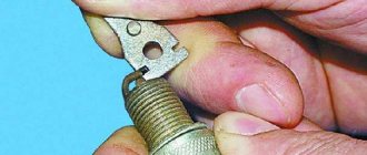
- It is necessary to connect the device wires to the module contacts, which are located at the edges. That is, to the extreme left and right. You can take a closer look at the photo below.
Ignition module
Causes and Symptoms of faulty spark plugs and ignition coils. Signs of faulty ignition coils
The ignition module is designed to generate the high voltage necessary to form a spark discharge between the electrodes of the spark plug.
Ignition module design.
The ignition module consists of two ignition coils with a closed magnetic circuit and a two-channel switch. But a twin ignition coil without a built-in switch is also called a module. In this case, the switch is displayed separately, but most often it is combined with the electronic engine control unit. Such modules can be distinguished by the number of wires on the connection connector. The ignition module with switch has four wires in this connector, but the twin coils have only three. This is due to the need to connect the negative wire to the switch, while the coils receive negative through a switch in the ECU or installed separately
This difference is very important when troubleshooting
Ignition module malfunction.
A malfunction of the ignition module is characterized by the absence of a spark discharge or a weak discharge on a spark plug, a pair of spark plugs, or all spark plugs.
It is important to use a spark gap when checking the spark discharge. Checking the spark discharge for a break or by connecting a spark plug placed on the housing to the wire can lead to failure of the ignition module or electronic engine control unit
The easiest way to check a module is to replace it with a known good one. But if this is not possible, then you will need to check the serviceability of the secondary coil by measuring the resistance between the terminals on spark plugs 1-4 and 2-3. The resistance value in this case is about 4 - 5 kOhm, the exact value depends on the manufacturer. But if the value is less than 4 kOhm, then most likely there is a turn short in the secondary coil, and if the module is new, then the manufacturer is saving money, which affects quality. Very high resistance indicates a break in the coil
When measuring resistance, you need to pay attention to the difference in resistance of the coils of one module. This difference should not exceed the instrument error value
The primary coil and switch can only be checked on a bench.
In addition to a malfunction of the coil windings in the module, the built-in switch may be faulty. The switch is made on a printed circuit board consisting of several microcircuits and filled with heat-dissipating gel. It is located on a metal plate at the back of the module, which serves as a heat exchanger. The specific switch design depends on the manufacturer. A common cause of commutator malfunction is poor contact between the commutator and coil connections. If you have the desire and experience in repairing electronic boards, you can try to disassemble and repair, but it’s easier to change the module.
Malfunction of the ignition module without a built-in switch (dual ignition coil)
In contrast to the module, the absence of a spark on the spark plugs with a dual ignition coil may indicate a malfunction of not only these coils, but also a malfunction of the electronic engine control unit. The thing is that the switch in this case is built into the ECU. On some foreign cars the switch can be made separately. In this case, you can check the coils by measuring the resistance of the windings. The actual resistance value varies by brand and manufacturer. For the primary winding, the resistance should not be less than 3 ohms, and for the secondary winding less than 4 kohms. But the difference between the coils of different pairs of terminals should not exceed the error value of the device used to make the measurement. A breakdown of the secondary winding to ground is also possible, although this happens extremely rarely. Finding such a malfunction is quite difficult, but the breakdown mainly occurs along microcracks on the body and breaks through only one terminal, and the spark disappears only on one spark plug of the pair.
Troubleshooting the ignition module.
The easiest way to find a faulty ignition module is to replace it with a known good one or replace the module being tested in a working car. The second way to determine serviceability with a degree of probability is to measure the resistance of the coil windings. Since the original value is almost never known, it is better to simply compare the value between the coils. The third, most accurate, but also the most difficult method is to check the module on a stand. In this case, the stand can be either factory-made or home-made. The latter can be made using a carburetor nine distributor driven by a drill. To check the double coil in this case, you can use a commutator from the same nine.
“If you notice an error in the text, please highlight this place with the mouse and press CTRL+ENTER”
Version of the module on the 8-valve VAZ-2110
The top ten was equipped with two 8-valve engines of different sizes - 1.5 (2111) and 1.6 liters (21114). The ignition modules for these engines are different.
- The one and a half liter engine has a module with article number 2112-3705010,
- and the 1600 cc is equipped with module 2111-3705010.
A module for a 1.5 liter engine costs about 1500-2100, and the second one is 500 rubles cheaper.
Which is better?
SOATE devices manufactured in Stary Oskol have proven themselves to be the most reliable ignition modules.
Module structure
The module consists of two ignition coils and two high-voltage switch switches.
Inside the module there is a board with radio components and ignition coils filled with compound.
The coil generates a high voltage pulse, and it is a simple transformer with two windings, primary (induction voltage about 500 V) and secondary (induction voltage at least 20 kV). All this is assembled in a single housing, on which there is a connector for signal wires (from the engine control unit) and four terminals for high-voltage wires.
Schematic diagram of the module.
The module operates on the principle of an idle spark - it distributes sparks in pairs to cylinders 1-4 and 2-3 according to impulses transmitted from the ECU.
Checking for errors
VAZ 2114 engine mounts signs of malfunction
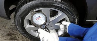
Checking the ignition device for malfunctions always concerns the location of the wires on the ignition module of the VAZ 2114. For simple diagnostics, we simply measure the resistance between the wires of the first and fourth cylinders and the second and third cylinders with a multimeter. If the indicator is 5.5 kOhm (switch the multimeter to ohmmeter mode!), then everything is in order. There are also other checks:
- The first thing to check is the wiring block; it is better to disconnect it and check it with a multimeter in voltmeter mode: we attach the multimeter probe to pin A, and throw the other one onto the ground of the sliders. We start and look at the voltmeter values: excellent. If the voltage fluctuates around 12 V. If there is no voltage, check the ignition coil fuse, it may blow, as well as the correct connection of all contacts. By the way, about that. Another way of checking can indicate that the circuit of contacts is closed incorrectly: by connecting a tester to both contacts - A and B - connect a multimeter to it; if it blinks, then the circuit is in perfect order.
- It’s worth checking all the high-voltage elements (with the same multimeter in ohmmeter mode); if they are installed incorrectly, the ignition coil will burn out.
- To understand whether the ignition module behaves correctly, move the wire block, you can knock on it. The contact should not disappear, if the engine responds to your movements, the contact is unclear. It can break at any moment.
Symptoms of an ignition coil malfunction are often displayed by the system during basic diagnostics in a service center (or in a garage environment via a connected laptop with a special program) in the form of errors:
- P0351 – break in the winding of wires of cylinders 1-4
- P0352 – break in the wire winding of cylinders 2-3
- P3000 (P3001 P3002 P3003 P3004) – the ignition does not work.
All these errors are motivation for a deeper diagnosis of the situation, on which the decision will depend: replace the module with a new one, or repair it. Also, these errors may indicate a possible malfunction of one of the spark plugs or an explosive contact.
Repair of the ignition module of a VAZ 2110 car
Usually the voltage disappears on the second and third cylinders. When pressing on the back plate of the ignition module, the power unit begins to operate in optimal mode. But this approach can hardly be called a repair. Therefore, the car owner must immediately check the functionality of the system and repair or replace the device. At the first stage, the module is dismantled. The procedure is performed in the following sequence:
- battery disconnection;
- dismantling the plastic cover installed above the upper part of the power unit;
- disconnecting wires from spark plugs;
- disconnecting wiring directly from the module. It is recommended to pay attention to the numbers indicated on the white rings. In this case, the cylinder numbers are indicated on the ignition module itself;
- disconnecting the connector from the device;
- dismantling the module block. The device is held in place by 3 nuts, which can be unscrewed using a 10 mm wrench;
- dismantling the device.
At the next stage, the VAZ 2110 ignition module is checked , as well as a set of troubleshooting works. First you need to open the block plate using a regular screwdriver. Inside the module there is a special board on which electronic elements are applied. To protect the surface, the board is coated with a layer of silicone. It must be carefully removed.
The contacts are connected to each other using aluminum wires. They are not durable. Therefore, it is recommended to immediately tear off all the wires. Instead, experts advise installing multi-core wires, which are used in computer mice.
The design of the device in question contains two transistors and two switches. Switches are manufactured by the SGS-THOMSON brand. The unit contains the L497D1 series. Transistors are represented by the BU931 line. This information will be needed by those car owners who want to change these parts. At the following stages of repair it is necessary:
- preparing flux for working with aluminum wiring;
- The wires are soldered to the board. Since the contacts of the switch and transistors are coated with a special substance, soldering is quite difficult. Therefore, it is first recommended to carefully remove the top coating;
- in order not to melt the plate, it is recommended to place the soldering iron on the stove and heat it to a temperature of 180 degrees;
- soldering should be carried out in such a way that the contacts remain minimal;
- The soldering surface must be varnished. To do this, you can use regular nail polish;
- then you need to check the ignition unit using a multimeter;
- if the device functions normally, the surface should be coated with automotive sealant;
- At the final stage, the structure is assembled in the reverse order.
Before assembling the structure, you need to make sure that the integrity of the contacts is not compromised. Checking the ignition module and soldering the considered elements is quite simple. Of course, the car owner will need professional skills, a meticulous attitude to work and compliance with the sequence of actions. First of all, this concerns soldering the printed circuit board.
The problem considered concerns exclusively bad contacts of the block. It is not difficult to identify the problem by pressing the back cover of the module. In some cases, pinout of the VAZ-2110 car device is required. Doing the work on your own is difficult. Therefore, most motorists turn to specialized services.
There are other problems, and you can spend a lot of time searching for them. Therefore, in some cases they resort to complete replacement of the device in question.
How to check the ignition coil with a tester on a VAZ 2106, as well as a VAZ 2109 and VAZ 2110 carburetor
Crankshaft position sensor, testing methods, symptoms of malfunction, location
On old VAZs it is not difficult to find a coil. It is located in a freely accessible area, under the hood. To check, you will need a regular multitester, which can be purchased for a small amount in many stores.
Video tutorial on measuring ignition coil resistance
The procedure is as follows:
- Disconnect the negative voltage on the battery. Disconnect the ignition coil wires, loosen the brackets. Clean the reel body. If obvious damage, cracks, etc. were discovered, it is better to immediately replace the device with a new one, since such a coil cannot be used.
- On the tester, turn on the ohmmeter mode. To check the “primary”, install probes or clamps on the side terminals located on the coil body. The tester display will show about 3.07-3.5 Ohm (original coil 2106 for a contact ignition system) or 0.45 ± 0.05 Ohm (coil 27.3705 for a contactless ignition system). For VAZ 2108, 2109 and 2110 - 0.43±0.04 (coil 3122.3705) and 0.42±0.05 Ohm (coil 8352.12). If the “primary” is broken or burned out, the resistance indicators will most likely tend to infinity.
- "Secondary" requires a similar check. But now the first probe goes to the side terminal, and the second to the central terminal. In addition, the indicators will be calculated in thousands of ohms. So, in accordance with the factory figures for the VAZ 2106 it should be 5400-9200 Ohms, for 2109 and 2110 - 0.40 kOhm (coil 3122.3705) or 1.00 kOhm (coil 8352.12).
- Also check the insulation resistance to ground. To do this, install one probe on the coil body, the second on each of the terminals in turn. The tester should show at least 50 mOhm.
The ignition coil cannot be repaired
Strong deviations from the normal range are a reason to replace the coil with a new one. It should be noted that this element of the ignition system cannot be repaired.
Checking the coil for VAZ 2101-2110
First, let's look at the sequence of checks on VAZ cars. Moreover, checking the carburetor for VAZ-2101 and VAZ-2110 is no different, the only difference is in the readings.
Next is the verification process itself:
- It is better to test the coil when it is removed from the car. Before starting removal, disconnect the negative terminal from the battery. From the coil we disconnect the wires from the side terminals, as well as the central wire. It is better to mark the wires from the side terminals so that they are not confused during installation.
- Loosen the coil fastening and remove it. Before checking with a multimeter, we clean it from dust and dirt, especially paying attention to the terminals. Then we inspect it for external damage. If there are any, further checking is pointless; it is better to replace it immediately;
- Checking the primary winding. To do this, switch the multimeter to ohmmeter mode and connect its probes to the side terminals. Different types of coils were used on different VAZ models, so you need to know which resistance readings are correct for them. So, for the B-117A model, used on classical models (VAZ-2101-2107), the resistance of the primary winding is 3.07-3.5
Ohms.
And on classic models with a contactless system, coils marked 27.3705
; this parameter is
0.4-0.5
Ohm.
On VAZ-2108-21099 cars, as well as VAZ-2110 carburetor, models with numbers are used - 3122.3705
and 8352.12.
For the first of them, the resistance of the primary winding is considered normal in the range of 0.39-0.47
Ohms, and for the second -
0.37-047
Ohms; - Next, the secondary winding is checked. To do this, switch the multimeter to the kOhm measurement mode, leave one of its probes on the side terminal, and connect the second to the central terminal. For a working B-117A coil, the resistance of the secondary winding should be 7.4-9.2
kOhm.
For model 27.3705 this parameter should be around 5.0
kOhm, for 3122.3705 -
0.4
kOhm, and for 8352.12 -
1.0
kOhm; - The last thing to check is the insulation resistance. To measure this parameter, switch the multimeter to measurement mode in MOhm. To measure, we connect one probe to the coil body, and connect the second to each terminal in turn. When measuring this parameter on all specified models, the multimeter should show at least 50
MOhm; - If any of the parameters does not match the specified values, then the coil is faulty and must be replaced.
How to check the ignition module on a VAZ 2114
An ignition module is needed in a car to produce high voltage current, which then ignites the spark plugs. On different VAZ vehicles, a separate or block ignition module can be installed. In separate type modules, there is a separate coil for each cylinder. In block modules, one coil is used for two or all cylinders at once. It should be noted that the block ignition module is much easier to remove, check and install back, compared to a separate one.
The VAZ 2114 is now available with a block ignition module; its coil design includes: a core, a winding, high voltage wires and low voltage terminals.
How does a malfunction of the ignition module manifest itself:
– idle speed floats; – engine tripping; – loss of traction with increasing speed; – the message “Check engine” error is displayed.
Note. Some drivers believe that high-voltage wires and the ignition module are completely different things, and if the wires become faulty, the module will not be affected. This is mistake. If the wires are damaged, the spark may not fire accurately, which can result in the ignition module burning out altogether.
The easiest way to check the ignition module is to install a similar, working ignition module instead of your own. If this is not possible, then you can get by with a multitester or a regular 12-volt light bulb (“control”).
Checking the serviceability of the ignition module using a multitester
Checking the health of the winding
Set the multitester to ohmmeter mode to measure the resistance between the terminals of the secondary winding. Install the probes on the leads to the first and fourth cylinders, then to the second and third (see video below). Usually the tester shows a result close to 5.4 kOhm (plus or minus 0.1 kOhm). The main thing is that the resistance between paired terminals is approximately the same. If the difference exceeds 100 Ohms, then this is evidence of failure of the secondary winding.
Solution to the problem: replacing the ignition module.
Checking the serviceability of high-voltage wires
You need to “ring” the wire block. Set the multitester to voltmeter mode, disconnect the wire block from the ignition module. Place one probe on contact A, the second on engine ground. Have someone start the engine (or turn the starter), and you note the display readings for yourself. Normally, the voltage should be around 12 Volts. Do the same manipulation with the other contact.
If there is no voltage at all, then you need to check the fuse: it may have blown. There are three fuses on the VAZ 2114 electronic control unit. The third one from the top, rated 7.5 A, is the fuse for the ignition module.
There may be no electric current not only due to a blown fuse, but also due to oxidation or broken wires or loose contacts.
Checking the serviceability of the ignition module using a “check”
If you don’t have a multitester at hand, a 12 V test light will help you check the ignition module. Connect one wire of the light bulb to the contact of block A, the other should be shorted to the engine body. Now let someone start the engine (or turn the starter), and you look at the light bulb - it should flicker. Do the same manipulation with the other contact.
How to remove the ignition coil of a VAZ 2114
1. Disconnect the negative terminal from the battery.
2. Remove the tips from the spark plugs.
3. Release the latch and disconnect the low-voltage wire block from the coil.
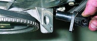
4. Unscrew the bracket mounting bolts from the gearbox and the lower mounting bolt from the cylinder block.
5. Remove the coil together with the bracket.
6. Disconnect the high-voltage wires from the coil.
7. Unscrew the bolts securing the coil to the bracket.
8. Remove the coil. How to check the ignition coil
On the coil, on each terminal there is a mark indicating which wire goes to which cylinder. There are also marks on the high-voltage wires. When installing the ignition module back, you need to take these marks into account. When changing a coil, the new coil must have the same markings.
Video: How to check the ignition module
Video: How to remove the ignition coil of a VAZ 21114
How to check input wires for serviceability
Following the recommendations of specialists, to check the condition of the wires at the input, they need to be “ringed”. What does it mean?
- Determine the operating format of the multitester in the voltmeter position, and then disconnect the wiring block from the VAZ-2114 ignition module.
- Focusing on contact A, mount the first dipstick, and fix the second one to the engine ground.
- Ask an assistant to start the car or, alternatively, crank the starter. At this time, your task is to observe the measurements on the display. Normal voltage is 12 volts.
- Carry out exactly the same actions with the remaining contact.
What to do if there is practically no voltage? Then evaluate the serviceability of the fuse - it is likely that it has blown. Find 3 safety mechanisms on the VAZ-2114 electronic control panel. So, the third 7.5 A is a device suitable for the car module.
Even if the fuse is intact and intact, there is a possibility of oxidation and wire breakage, as well as loose contacts.
What to do if there is no multitester available? A control light designed for 12 V will help solve the problem. One wiring of the lighting device is placed to the contact of the block, and the other is closed to the motor housing. After turning on the ignition, the light should flicker.
How to check the VAZ-2114 ignition module with your own hands is shown in the video instructions:
How to check the ignition module yourself
Let's say you have clearly determined that the engine is malfunctioning (maybe another malfunction) due to the ignition module. You know where it is located, the pinout of the input block is known. To decide whether to repair the module or replace it with a new one (this is your cost), we will test it at least with a multimeter.
The easiest way is to replace the unit with a known good one. This is only possible if you have a good friend with a similar car. With such a check, the so-called “support group” - cables, electronic switch. Performance of the contact group
While the motor is running, press on the plugs of the high-voltage wires (Caution!) and the control block. If the nature of the motor’s operation has changed (it does not oscillate, the speed has become stable), check the condition of the contacts. We measure the resistance at the coil contacts
Secondary windings are guaranteed to be tested. Between the output contacts of 1.4 and 2.3 candles, the resistance should be the same and within 5 Ohms. We examine the disassembled module. Of course, you need to have basic skills in electrical engineering (the level is somewhat higher than “screwing in a light bulb in a hallway”). Broken wires or burnt contacts are immediately visible, and the serviceability of transistors can be checked with a multimeter. The primary winding of the coils becomes accessible.
If the parts are replaceable, we carry out repairs. Wiring and contacts are restored simply.
Module check
After signs similar to failure of the ignition module appear, it must be checked before buying a new one, since its cost is not cheap.
There are three ways to check: substitution, visual inspection and a multimeter.
Substitution
The best and easiest way to check the MZ is to install another known good one from another exactly the same car. After which it will immediately become clear what the matter is and whether the Ministry of Health is to blame for this problem.
Visual inspection
It is necessary to inspect the module for chips, cracks, etc. There should be no damage to it. There should be no moisture or rust on the contact part.
Multimeter
Testing with a multimeter is carried out using the results of voltage and resistance measurements. This will help identify the cause of the failure of the module or its control circuit.
Step by step check
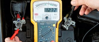
- Remove the power supply from the module. On the multimeter we set the DC voltage measurement limit to 20V. We turn on the ignition on the car and connect the multimeter contact on one side to the power block (namely to connector 15), and on the other side to the engine housing. The voltage between pin 15 and the motor housing must be at least 11-12V. Otherwise, the power supply circuit of the MH is faulty, or the battery is discharged.
- Next, we check the resistance on the VAZ 2110 ignition module itself. We set the multimeter to the resistance measurement parameter, namely 200 Ohms. We connect the multimeter probes to the high-voltage terminals of the MZ: 1-4, 2-3. The resistance of these coils, with a working MC, should be within 5 ohms.
- Then the resistance at the MC input is checked. One multimeter probe is connected to the central contact and the resistance is measured first on the leftmost contact and then on the rightmost one. The resistance should be in the 5 ohm range.
How to improve the spark or modify the circuit of individual VAZ ignition coils
| The problem of floating engine speeds, sluggish acceleration with jerks and increased fuel consumption are familiar to almost every owner of a VAZ car. One of the reasons for these ailments lies in the ignition system. Let's consider the modification of individual ignition coils (ICC), which will help cope with unstable sparking. |
What is the reason
- dips need to be smoothed out by installing capacitors, as close as possible to the load itself;
- simplify the power supply chain of the IKZ.
Installation of capacitors
- it is possible for a higher voltage 35/50/63V, but not 16V;
- capacitance range 3000 - 4700 µF, the upper limit does not need to be exceeded;
- recommended manufacturers: Jamicon (TX, TL, TZ, WG, TK, TM), Samwha (WB, WF, WL, RD), CapXon (KF, LZ, KM, GL);
- 105 degree, low impedance (LowESR).
- We cut the insulating tape of the IKZ harness under the corrugation between 2-3 cylinders, we find 5 blue wires. We connect the plus of twisted capacitors to twist S1.
- In order not to touch the twist, you can solder the positive wire of the capacitors to the lead (thick) blue wire that comes from the ECM connector (stripe 5-8mm in a circle).
Result
- ─ the car accelerates better;
- ─ failures disappeared;
- ─ response to the gas pedal has become clearer;
- ─ idle speed became stable;
- ─ gasoline consumption decreased by 0.7-0.9 liters to 7.8 l/100 km in the city.
- ─ the engine starts faster, the starter does not turn for more than 2 seconds.
xn--2111-43da1a8c.xn--p1ai
Ignition module diagram 2115
The ignition module installed on the Lada Samara is extremely resistant to both low and high temperatures. Operating temperature range: -400/+1300C.
The only negative point in the operation of this electronic device is its complete inability to repair. However, even a novice car enthusiast can replace it on his own.
Experts consider the most common malfunctions of the Samara ignition module to be:
- Unstable operation of the power plant when accelerating the vehicle.
- Decrease in engine power.
- “Intermittent” idle speed.
- Malfunction of paired (1/4 – 2/3) engine cylinders.
We check the ignition module on the injection VAZ-2110 8 valves with our own hands
At different times, different engines were installed on the VAZ-2110 car, both carburetor and injection. However, regardless of the type of power system and the number of valves (8 or 16), all engines are assembled on the unit base of the old engine 21083 and 21093. The most progressive of these engines is the 16-valve 1.6-liter VAZ 21124 engine with a power of 89 horsepower. Today we will touch on the ignition module for 8-valve engines 2111 and 21114 (1.6 l), check its performance and find a suitable replacement for the failed module.
The principle of operation of the ignition coil.
The module is a kind of connecting link: from the electronic control unit, which controls its working process, a certain signal is sent to the winding (in the form of charged pulses); then, the module produces high voltage, which is transmitted to the spark plugs through high voltages. This action allows the candles to produce the necessary spark to start the internal combustion of the air-fuel mixture in the chamber space.
The new generation VAZs, including the fourteenth, are equipped with an ignition system coil; it is not included in the general module, since its other important part - the switch - is located in the electronic unit. If you take the old-style VAZs, including the fourteenth with a 1.5-liter engine, then they have an ignition system module: two coils and two switches in a single housing. Two coils are connected to the cylinders by high-voltage wires (each for two cylinders: one for the 1st and 4th, the second for the 2nd and 3rd). The most experienced ladies get high only if the dick penetrates deep into their anal, the rest is all kindergarten. Watch deep anal porn, here the girls bring their partners to extreme bliss, squeezing their dicks with a tight asshole until the sperm flows like a river.
Signs of a faulty ignition coil:
- When accelerating you feel a failure,
- Power drops
- At idle the engine behaves unstable,
- The engine has problems (cylinders fail).
Before deciding what to do with a failed ignition coil, you need to check it. No special skill is required, just know what a multimeter is and how to hold it in your hands. Depending on the test result, you should make a decision: replace or repair.
In principle, the fundamental malfunction of the ignition coil is always the lack of normal contact. Maybe the mass has broken, maybe the contacts are stuck or oxidized. A small deposit of dust can put an entire cylinder out of working order, not to mention a modest module.
Along with possible module malfunctions, it is recommended to check all sensors - from mass air flow to DS - there is a serious possibility of failure of one of them.
VAZ 2114 ignition module replacement, malfunctions, repair
The ignition module in a VAZ 2114 car is an improved starting system. The device produces cycles that produce a spark - the engine starts. The ignition module creates high voltage current and then transmits it to the spark plugs through four high voltage wires. Among motorists, the device is called an “ignition system coil.” The electrical network of the VAZ 2114 powers the module, its “minus” is attached to the car body. It consists of:
- Ignition coils;
- Small plastic case;
- Electronic units;
- High voltage transformers;
- Outputs for connection.
The signal is transmitted to the electronics by the controller, which processes data on the functioning of the VAZ 2114 systems. The controller reads data from the sensors and then sets a certain sequence. The ignition coil is highly resistant to temperatures; withstands from -40 to +130 degrees Celsius.
Malfunctions of the VAZ 2114 ignition module
Determining that a module has malfunctions is not so difficult. One of the signs is a decrease in engine power of the VAZ 2114 or acceleration in jerks. If the unit malfunctions, the engine begins to operate intermittently when idling. If such “symptoms” are present, then it is necessary to check the serviceability of the spark plugs and the fastening of high-voltage wires, as malfunctions may appear due to these elements.
Checking the VAZ 2114 for malfunctions must be carried out in compliance with safety precautions: hands must be wearing rubber gloves, and tools must be isolated. If the spark plugs and wires are in perfect order, the module needs to be replaced. You can find it under the hood; the device will reveal itself as large high-voltage circuits, from which replacement begins.
In order not to make a mistake with connecting the wires when replacing, it is advisable to plug the high-voltage wires into their sockets and then label each of them. Then the new ignition coil can be connected, following the wires from the old one. Modern units have numbering that will help you figure out the connection. Marking will be useful if you buy an old-style module without numbering on the outputs.
Module replacement
Replacement is carried out using a hexagon, a 10' head and 13' and 17' keys.
- You need to disconnect the negative terminal from the battery.
- Then remove the wiring harness.
- Pull out the signed high voltages.
- Remove all fastenings to the motor.
- After these steps, the faulty element will be exposed to the motorist. You can get it out using a hexagon.
Replacing with a new unit begins with connecting high-voltage wires. There should be hints on the case, but you can use your own. The wires should also be carefully examined - they should have marks that indicate the cylinder number. For example, if the number “2” is on the wire, then it is intended for the second cylinder. Replacement is complete. Now you need to start the VAZ 2114 engine and check whether the module is secured correctly. If necessary, tighten the fasteners.
Repair
Before going to a car dealership to buy a new module, it is recommended to check the device contacts. If they fail, you can do the repairs yourself and not spend money on a new module. To check, you need to start the engine at idle and try to press the module cover with an insulated tool. If the engine starts working normally, then the problem is in the contacts. The work is not difficult, but quite painstaking, and you will need skill in handling a soldering iron. For repairs, you need to stock up on small and thin wires, varnish, a soldering iron, a screwdriver and flux for soldering aluminum.
Process:
- You need to dismantle the device according to the instructions described above.
- Next, you need to remove the housing cover; to do this, press down with a screwdriver. If the device is not standard, there may be bolts there.
- On the board you can see whether the guesses are correct or not.
- If the contacts have come loose, then you need to strip the board of small wires and replace them with new ones.
- A problem may arise with transistor controllers - they are covered with a protective layer that the soldering iron does not take. It can be cleaned with improvised materials or a burr machine.
- Small wires need to be replaced.
- The final step is to cover the soldering areas with varnish or silicone. Even nail polish will do. That's all.
note
Repair
Ignition module VAZ 2107
The design of the ignition module is quite complex: it includes one or more coils, a board, contacts and wires. Of all the above elements, only contact connections can be repaired; in some cases, replacement of parts (transistors, coils) is possible.
The module is dismantled and opened for repair purposes. For this you will need:
- Socket wrenches with heads 1, 13 and 17.
- Hexagon 5.
- Screwdriver.
- Soldering iron.
- Flux for aluminum.
- Stranded wire.
- Nail polish.
Opening the ignition module
Repair of the ignition module is carried out in the following order:
- On the removed device, open the case by prying it off with a screwdriver.
- Remove the silicone film covering the board.
- All aluminum is removed from the explosive contacts.
- On the board, new wires are soldered in place of all the dismantled old ones. To do this, the surface of the collector is cleaned of deposits, after which the board is heated to 180 o C (a characteristic smell will indicate when the desired temperature has been reached). During the soldering process, the ends of the wires are connected to the module.
- At the end of the operation, all contacts, the board and the module are covered with nail polish.
- The device is assembled in the reverse order, installed on the car and the engine is started. In case of normal operation, the ignition module is sealed tightly with sealant, while the wires are tucked inside the cavity so that they are not pinched at the edges by the plate.
If the device does not work, then a breakdown inside the module should be looked for more carefully. The transistor, electronic component may have failed, or there may be a break in the coil. Such a repair makes sense only if its price is significantly lower than the cost of a new part.
To quickly check the serviceability of the ignition system, you can use a spark indicator for engines with fuel injection. It is put on the spark plug, and a high-voltage wire is connected to it. When checking, you must follow the instructions supplied with the device.
The 11183 (1.6i) engine uses an ignition coil. The 2111 (1.5i) engine may have an ignition coil or ignition module installed (see System Description). The ignition coil replacement is shown below. Replacing the module is done in the same way.
To complete the work, you will need a multimeter (in voltmeter and ohmmeter mode).
1. Prepare the car for work (see “Preparing the car for maintenance and repair”), turn off the ignition.
2. Having released the latch, disconnect the wiring harness block from the ignition coil (module) terminals.
3. Turning on the ignition, use a voltmeter to measure the voltage between terminal 15 and ground (for the ignition coil) or terminals C and D (for the ignition module) of the wiring harness block.
The voltage must be at least 12 V. If the voltage is not supplied to the block or it is less than 12 V, then the battery is discharged, the power circuit is faulty, or the ECU is faulty. You can verify that the ignition module is faulty by replacing it with a known good one. The ignition coil can be checked with an ohmmeter.
After taking measurements, turn off the ignition.
4. Disconnect the high-voltage wires from the spark plugs (see “High-voltage wires - checking and replacement”).
13 mm socket wrench
Unscrew the two bolts of the upper fastening of the ignition coil bracket.
6. 17 mm
Having loosened the lower bolt securing the ignition coil bracket, remove the bracket together with the coil.
7. Disconnect the high-voltage wires from the ignition coil (module) (see “High-voltage wires - checking and replacement”).
What determines the performance of the coil?
The classic ignition coil or “bobbin”, as it is also popularly called, is essentially a low-voltage voltage converter from the battery and generator to high-voltage, which is then supplied to the spark plugs. That is, this is a miniature electrical transformer.
The ignition coil is a kind of mini electric transformer
The traditional coil, used on carburetor models of vehicles, consists of two windings. The primary winding receives low voltage pulses, for example 12 Volts. As a rule, this is a small number of turns (up to 150) of thick insulated copper wire. The “primary” has 2 terminals on the coil cover. There are much more turns in the secondary winding - up to 30 thousand, but the wire used is much thinner. One end of the “secondary” goes to the “minus” of the primary winding, the other to the central terminal of the coil. In the center of the windings there is a core that enhances the magnetic field. The coil body is insulated, and its cavities are filled with special oil for transformers.
The fundamental characteristic that indicates the serviceability of almost any coil is the resistance of the windings.
Check for Lanos, Tavria, Reno Megane
The difference in checking the ignition module on a Daewoo Lanos is no different from testing the VAZ-2110 module.
The differences come down only to the resistance of the secondary winding at the module terminals. For Lanos, the resistance of the secondary windings of a working module should be in the range 5,0-6,0
kOhm
As for a car like Tavria, the 1102 model uses a contactless system, so checking the coil is identical to checking on VAZ 2108-21099 cars.
But the Tavria Slavuta uses a module that is tested, just like the Daewoo Lanos.
The procedure for checking the ignition module on many foreign cars is identical to the indicated methods.
On the same Reno Megane, the module is also checked by measuring the resistance of the secondary windings.
Checking the ignition coil is a simple operation and can be completed within a few minutes. But taking measurements will definitely make it clear whether this element is the cause of interruptions in the operation of the motor or not.
Troubleshooting the ignition module.
The easiest way to find a faulty ignition module is to replace it with a known good one or replace the module being tested in a working car. The second way to determine serviceability with a degree of probability is to measure the resistance of the coil windings. Since the original value is almost never known, it is better to simply compare the value between the coils. The third, most accurate, but also the most difficult method is to check the module on a stand. In this case, the stand can be either factory-made or home-made. The latter can be made using a carburetor nine distributor driven by a drill. To check the double coil in this case, you can use a commutator from the same nine.
admin03/07/2016
Ignition, Devices
A comment
Name *
Website
This site uses Akismet to reduce spam. Find out how your comment data is processed.
« Kan-shina
Immobilizer flashing »
Tags
VAZ, VAZ malfunctions Sensors Ignition Injector Devices Starter Circuits Electric cars Power supply VAZ 2110 gazelle gazelle business recorders car repair
Recent Entries
- Design and principle of operation of parking sensors
- Multifunctional device Roadgid X7 Hybrid GT
- Malfunction of the GAS ignition system
- Electric Xiaomi Mi Mijia M365
- Additional vehicle equipment (installation)
Archives
Archives Select month August 2022 July 2022 December 2022 August 2017 July 2022 June 2022 May 2022 April 2022 March 2022 December 2016 November 2016 October 2016 September 2016 August 2016 July 2016 June 2016 May 2016 April 2016 March 2016 February 2016 November 2015 October 2015 August 2015 July 2015 June 2015 May 2015 April 2015 March 2015 February 2015 January 2015 December 2014 November 2014 October 2014 September 2014 August 2014 July 2014 June 2014 May 2014 April 2014 February 20 14 January 2014 December 2013 November 2013 October 2013 August 2013 June 2013 May 2013 March 2013 February 2013 January 2013 November 2012 October 2012 September 2012 August 2012 July 2012 June 2012 May 2012 April 2012 March 2012 February 2012 January 2012 December 2011 November 2011 October 2011 November 2011 August 2011 July 2011 June 2011 May 2011 April 2011
Categories
- Accumulator battery
- Video
- Generator
- Sensors
- Diagnostics
- Ignition
- News
- Equipment
- Devices
- Repair
- Spark plug
- Starter
- Scheme
- Devices
- Electric cars
- Electricity supply
We are in social networks
Autoelectrics@ All rights reserved. When copying site materials, you must provide a link to the site.
Cost and alternatives
In the vast majority of cases, it is poor contacts, as well as the transistor and switch, that cause the failure of the ignition module in a VAZ-2110 car.
If a problem is detected, you can perform soldering yourself. In this case, you will need to purchase a switch, which costs about 6 US dollars. In turn, purchasing a transistor will cost approximately $3.
There are alternative options, for example, the KT848A transistor. But this semiconductor device is large. Therefore, additional difficulties may arise when performing repairs. Experts also note that the analogue is of low quality. Therefore, saving is not recommended. Finally, we note that you need to buy any spare parts, consumables and accessories only in trusted online stores.
How to check
Checking the VAZ 2114 ignition module begins with preparing the equipment. And the best diagnostician in this case would be a device for checking the ignition module such as an oscilloscope. Unfortunately, not every Russian driver has an idea of what it is, not to mention the ability to use it. Therefore, we focus on the end consumer and use available means:
- 12-volt light bulb or control in common parlance
- Tester, it can be purchased for pennies at any spare parts store
Before touching the module itself, pay attention to its accompanying parts. We start with the wire block, it’s worth disconnecting it and checking the voltage
To do this, we fix the tester terminal on contact A, and throw the other one onto the ground of the sliders. Normal voltage is 12 V. If it is not there, then the problem is clearly in the fuse. It's a different story with him. Next, along the wires: we throw the tester terminal onto contacts both A and B. We start, the starter starts, the control indicator should ideally blink. If this does not happen, then the problem is a break in the contact circuit A.
Now directly to the ignition module. There are several options for diagnosis:
- One of the simplest types of diagnostics is to replace a non-working unit with a working one. Of course, for this you need a “donor”. We replaced it, looked at it, and drew conclusions. The only thing that can be an obstacle is that you need an identical unit, that is, a friend with the same car of the same year as yours. Because for 1.5 engines it is the module that is used, and for 1.6 engines only a coil is used. And remember about the working explosive wires, if they fly, then the module is bent because of them. Again, checking BB contacts is a different story.
- You can do it differently - move the ignition unit. What does this mean: you need to shake the block with contacts, then hit the module and shake it. At this time, the engine itself must be running, because all these actions are necessary in order to see whether its operation will remain flawless when staggering. If not, then again take a closer look at the wiring.
- Another way: put the tester in the operating state of the ohmmeter. We measure the resistance on the explosive wires that go to cylinders 1 and 4. And then - to 2 and 3. The normal resistance is considered to be from 5.2 to 5.5 Ohms.
Important: the ignition module most often cannot be repaired. Or is the repair not worth it?
It's easier to buy a new one and install it.
You can buy an ignition module for a VAZ 2114 anywhere and anytime, the price is not that steep - from 2,000 to 4,000 thousand rubles, depending on the region and the quality of the unit (manufacturer, new or used). But, if you decide to get confused, then be sure to look at the information on how to check the serviceability of the ignition module.
If you still doubt your own abilities, the doors of the service are always open for you. Moreover, the ignition module itself can be of both domestic and foreign production. But, no matter how strange it may sound, a qualified mechanic will most likely use all of the above techniques for the process, because he knows how to check the ignition module on a VAZ 2114. With rare exceptions, you can find someone in the service who will use an oscilloscope. Therefore, ride it once and see how and what is being done. At least some benefit from the time and money spent is a clear example for independent garage diagnostics.
We recommend
- Phase sensor errors on VAZ 2114
- Replacing the voltage regulator on a VAZ 2114
- How to replace the license plate light bulb on a VAZ 2114?
- Replacing the phase sensor on a VAZ 2114
https://nadomkrat.ru
What is ignition module diagnostics?
As you probably already understood, electronic ignition can easily fail, in principle, similar to other components of the car. Therefore, if this happens, you should have in your driver’s arsenal several effective methods that will help you determine which mechanism failed? It is quite possible that this is the ignition module. How to check? It’s as simple as shelling pears, the main thing is to take a tester or multimeter, as well as a test lamp, to the garage. When performing the check, I use several effective methods that will help you one way or another. Please consider!
- A banal replacement - provided that the new mechanism is functional and identical to the old module.
- Resistance measurement - switch the tester to ohmmeter mode and measure the resistance at the paired terminals, to be precise, between cylinders 1 and 4, as well as cylinders 2 and 3. The readings on both sides must be identical. What should the resistance be? This figure can fluctuate around 5.4 kOhm.
- Voltage measurement - fix one multimeter probe on the block, namely on contact A, the second on ground. Turn on the ignition; if the lead breaks, the device will not provide you with any information; otherwise, familiar numbers will appear on the dial - 12 V.
- Checking the circuit for breaks - attach the end of one wire of the test lamp (12 V) to contact A and activate the starter. If the circuit is working properly, the light should blink; if there is a break, it should not blink. Do the same with other contacts.
- Trust the professionals - a specialized check at a service station, the best option for those who do not save on their own car.
Signs of a malfunctioning ignition module
The list is relevant only if the other systems (spark plugs, injectors, crankshaft position sensor, cylinder compression, fuel system) are in good working order and operate according to the established parameters. The symptom of a faulty spark plug may not differ from a banal loss of contact between the ignition module and the high-voltage cable.
- Troubles the engine. In fact, there are many reasons, but the main culprit is our module. Moreover, this could be a contact phenomenon, or a breakdown of the radio element. A clear sign of coil failure is that failures occur in two cylinders simultaneously. That is, candles either Nos. 1 and 4 or Nos. 2 and 3 “do not burn.”
- The engine thrust has noticeably decreased. The car does not hesitate, it runs smoothly, but acceleration uphill or under load occurs lazily.
- During sharp acceleration, a kind of failure of thrust occurs in the engine. It's as if the fuel pump is not performing enough. If the gas tank is in order, look for the cause in the ignition module.
- At idle the speed fluctuates (of course, with the IAC running).
And of course, the “check engine” alarm. If the fault is detected by the ECU module, this is good for diagnosis. You can read OBD errors in any available way:
- using electronic odometer codes (if such an option is available);
- using the on-board computer, if it has a decoding function;
- any diagnostic scanner, for example, ELM327 paired with a smartphone.
If you recognize error codes associated with misfires specifically in a pair of spark plugs, the most likely cause is a faulty ignition module.
Checking the ignition coil and its circuits
Misfires during engine operation can be caused not only by faulty high-voltage wires, but also by failure of the ignition module. To identify a malfunction of the ignition coil on the Lada Kalina, we will need a multimeter with which we will measure the resistance at its contacts.
The passenger car ignition module is specially designed to improve the starting of a car engine. Since two high-voltage coils operate as the main components of the module, it is often called the “ignition coil”.
The ignition module is controlled by the ECU, which supplies constant voltage in the form of low-voltage control signals to the windings of its coils at the right moment. The end of the signal is the beginning of the spark. Thanks to magnetic induction, at the moment of application, a high voltage is generated, creating a spark at the spark plug.
If one or more cylinders in the engine do not work, acceleration failures are possible. The car will twitch and vibrate.