A speed sensor (DS) is structurally provided on every car. It is designed to determine the speed of movement of the car and transmit the received data to the dashboard, or rather to the speedometer.
It is prohibited to operate a vehicle with a faulty speedometer, as this can lead to an accident or fines from the traffic police.
If the product breaks down, checking it does not take much time, and to complete the work you only need a multimeter or test lamp.
What is the device? What does it look like and where is it located? What are the signs of malfunctions, and how to check the speed sensor? These and other questions will be addressed in this article.
First, we will look at the main testing methods, and then we will touch on individual models: Lada Kalina, Priore, Granta, Gazelle, Nissan, Niva, VAZ 2110, VAZ 21093 injector.
Purpose and location
As we noted above, the sensor determines the speed of the vehicle and transmits the received data to the speedometer, where they are reflected. Speedometers are either pointer or liquid crystal.
The shaft is the main element of the product. It rotates and passes near a special mark once per circle. At this moment, a pulse is sent to determine the number of revolutions per minute.
The number of signals depends on the rotation speed of the shaft, the value of which is coordinated with the transmission shafts and wheel diameter. Thanks to this, information from the speed sensor is converted and sent to the speedometer.
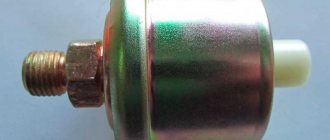
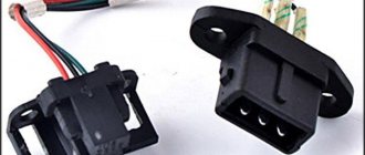
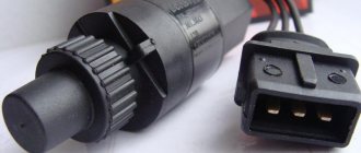
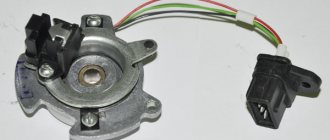
The DS consists of three elements - the speedometer drive, the casing and the controller, through which the product is connected to the vehicle's electrical network. Depending on the make and model of the car, the appearance and design may vary.
The location of the speed sensor is also different. Before checking it, you need to find the device.
Common mounting locations are the transmission output shaft or transfer case (for all-wheel drive vehicles).
Older models used a cable that was screwed onto the speedometer drive. Today its place is taken by a speed sensor, connected using ordinary wires.
Description of DS
As we have already said, the main purpose of the speedometer drive sensor is to accurately determine the speed of the vehicle. Thanks to this device, the model can always know at what speed his car is moving. As for the varieties, DS can be of the contact or non-contact type. Today, most of our compatriots prefer contactless options. Contact DS, despite all the advantages, have one significant drawback - they are prone to contamination, which in turn will lead to inaccuracy of the displayed readings.
Design and principle of operation
Structurally, according to the diagram, this part consists of:
- speedometer drive;
- housings;
- as well as the controller itself with a connector for connecting to the on-board network.
As for the principle of operation, it is based on measuring the frequency level of signals from the controller, which is located on the gearbox housing or transfer case. At the output of the device, while driving, rectangular pulses are formed, the minimum value of which should be at least 1 volt, and the maximum value should be at least 5 volts.
According to international standards, the controller must generate about 6 thousand such pulses over one kilometer. The pulses themselves are subsequently converted into current, which is measured by a magnetoelectric device. It should be noted that the current value directly depends on the number of signals supplied per certain unit of time. That is, this value will be directly proportional to the speed of the vehicle.
In addition, thanks to the electronic circuit installed in the dashboard, the operation of the stepper motor is ensured by counting incoming signals. The latter is designed to rotate the counter reels, after which it displays the relevant information on a small screen, where the total and daily mileage of the car is shown. If we are talking about daily mileage, then this value can be reset to zero if necessary.
Symptoms of a problem
If the DS for some reason fails, this will lead to the control unit being unable to determine the speed of movement. However, this is not the only problem, since malfunctions in the performance of the power unit may also occur.
We suggest that you familiarize yourself in more detail with the signs of a malfunction, by which you can determine the failure of the DS:
- the speedometer on the dashboard has either stopped working altogether or displays incorrect readings;
- malfunctions appear in engine operation, in particular at idle speed;
- fuel consumption increased;
- engine performance has deteriorated, the power unit cannot reach the required speed;
- the engine may stop spontaneously while idling, in particular when the driver tries to press the clutch to change gear;
- if the car is equipped with an on-board computer, a Check indicator may appear on the dashboard;
- if the car is equipped with an electric power steering, this unit may also fail;
- in some cars, for example, Lada Kalina, failure of the diesel engine can also lead to increased sensitivity of the fuel level controller in the gas tank (the author of the video is the Autoelectrics HF channel).
As for the reasons, as a rule, they are caused by damage to the car's electrical wiring, so checking the functionality should begin with diagnosing the condition of the contacts and electrical circuits. Perhaps the problem lies in oxidized or dirty contacts, so they will need to be cleaned and treated with a lubricant, for example, Lithol. A broken wiring should be looked for first of all near the connection connector, since in this place the wires are bent and usually frayed.
When is a check needed?
Checking the DS is necessary for the following symptoms:
- unstable engine operation at idle;
- the speed of the machine is shown incorrectly;
- in normal operation, the car consumes more fuel;
- the speedometer does not show information (in case of complete failure);
- deterioration in acceleration dynamics;
- error information appears on the central display.
These signs may indicate other failures, for example, those related to the fuel or air systems.
Therefore, before making a final “verdict”, the speed sensor must be checked, and if the malfunction is confirmed, it must be replaced.
Operating principle of the speed sensor
The operation of the speed sensor is based on the Hall effect. Pulses from the device are sent to the car's ECU, where they are converted into the necessary readings. It is known that 6000 pulses are transmitted per kilometer. The faster the signals arrive at the ECU, the higher the movement speed.
The electronic control unit receives impulses, processes them and provides information to the speedometer in a form understandable to humans. To determine the speed, a special algorithm is installed in the ECU.
As noted, the operation of the speed sensor is based on the Hall effect - a physical phenomenon that implies the appearance of voltage when a conductor is placed in a magnetic field.
While driving, rectangular or wave-shaped signals with a voltage of 1 to 5 Volts appear at the output of the product.
The use of a special scheme and program allows you to calculate the current speed of the car and other important parameters - average daily mileage, total distance traveled and other data.
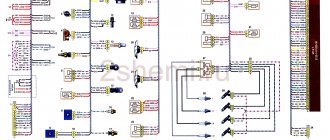
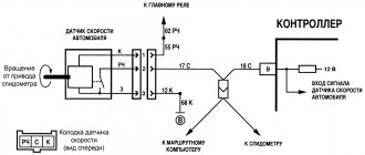
For the advanced, below is a schematic diagram of how a car speed sensor works.
How does it work and where is the speed sensor located?
Although this device does not mechanically affect the movement of internal combustion engine parts in any way, it performs a useful function, namely, the speed sensor transmits data with errors that adversely affect the quality of engine operation. The speed meter transmits signals to the sensor that controls the overall operation of the internal combustion engine at idle speed, and also, using the IAC (idle speed controller), regulates the air flow that bypasses the throttle valve. The faster the car's wheels spin, the more signals are transmitted.
The speed sensor device operates on the basis of a Hall sensor. During engine operation, the DS sends pulse-frequency signals to the electronic control unit (ECU) at certain short intervals. For one kilometer of distance traveled by a car, the speed sensor sends about 6 thousand signals to the ECU. Using the signals received from the DS, the ECU determines at what speed the car is moving.
What is the Hall effect? The Hall effect is when you place a conductor carrying a constant current in a magnetic field, an electric voltage appears.
In designs of various brands and models of cars, the speed sensor is installed both next to the speedometer and next to the gearbox. But did you know that there is such an incoming air temperature sensor, based on the readings of which the on-board computer decides how much fuel and air to supply.
If the operating principle of the DSA is based on the Hall effect, the speed sensor is checked in three ways. For the first two you will need a multimeter. In the third case, you can get by with a regular light bulb.
The first method of checking the sensor requires removing it and using a multimeter to find the pulse contact and connect the positive probe of the device to it. The second probe is attached to the body or car engine. After this, a small tube is put on the DSA axis and rotated, checking the voltage with a multimeter. As the rotation speed increases, the number of pulses should also increase.
For the second method, you will need a jack, which can be used to lift any front wheel of the car. A multimeter is connected to the sensor wires and rotation begins. The faster the wheel spins, the more pulses the device registers. If this rule is not followed, then the sensor is faulty.
For the last method, you will need a 12-volt light bulb, which will be used instead of a multimeter. The wheel is lifted with a jack, and the lamp is connected to the DSA pulse wire. Its blinking when the wheel rotates proves that the device is working.
The operation of the speed sensor is based on the Hall effect: the sensor supplies the controller with a pulse-frequency signal. In this case, the frequency of the pulses that are supplied to the ECU is directly proportional to the speed at which the wheels rotate. The engine control unit receives signals from the speed sensor, calculates the interval between pulses and, in accordance with this, calculates the vehicle speed. For every kilometer traveled, the speed sensor produces approximately 6 thousand signals.
Typically the speed sensor is located on the gearbox: it is located directly on the speedometer drive mechanism.
The DS device is based on the Hall effect; the device transmits pulse-frequency signals to the ECU at certain intervals. So, over one kilometer of travel, this device transmits about 6,000 signals and, based on the data received, the control unit automatically calculates the speed of the vehicle.
The higher the speed of the car, the more intense the pulses arrive at the controller. In addition to determining the speed, this device performs another important function. When the car is coasting, the pulse sensor does not block the flow of fuel, thereby contributing to savings.
Today it is customary to distinguish several types of DSAs, differing in design: inductive, reed and based on the Hall effect (electronic sensors).
The speed sensor works thanks to the Hall effect. The device supplies pulse-frequency signals, the control unit is responsible for decoding them. The main idea of the designers who created the device was that the pulse frequency is proportional to the speed of the vehicle.
Attention! The speed of a car is the speed at which the wheels rotate.
Many processes occur in the control unit while reading readings from the speed control sensor. Thanks to them, the system is able to calculate the length of the intervals between pulses, and based on them, calculate the speed of the machine. In just one kilometer the car travels, the device sends more than six thousand signals.
Part placement depends on many factors. This is not surprising, because every automobile manufacturer tries to achieve maximum performance at minimum cost. But if we take into account the main trend, the device is located on the gearbox. It is easiest to access from below.
DETAILS: Fines for speeding in 2022
Signs and causes of malfunction
Symptoms indicating the need to check the speed sensor have already been indicated above. The main signs of a malfunction are the absence of readings on the speedometer, increased “gluttony” of the engine, malfunction of the engine at idle, deterioration in dynamics, etc.
A breakdown of the sensor may be indicated by engine stopping while driving, failure of the electric power steering wheel, or increased sensitivity of the FLS (for example, for Lada Kalina).
Common causes of sensor failure:
- violation of the integrity of contacts;
- oxidation at joints;
- open circuit;
- insulation melting;
- wear of the speedometer cable, etc.;
- strong vibration of the device;
- dirt ingress;
- temperature changes;
- Other reasons.
If you ignore problems, engine malfunctions occur and wear on its elements increases.
As a rule, the cause of problems is dirty contacts, which should be cleaned and treated with Lithol.
If there is a break in the electrical circuit, the damage should be looked for near the connection connector. This is where the wires are most susceptible to bending and breaking. Sometimes the insulation becomes damaged where the exhaust manifold is mounted.
When exposed to high temperatures, the insulation can be damaged, which leads to short-circuiting of the wires.
With prolonged use, the speedometer cable wears out, which eventually develops cracks and breaks, which leads to failure of the controller.
An equally common cause of speed sensor failure is a broken circuit, so before replacing the device you need to make sure it is working properly.
To begin with, you should discard the power supply and examine the contacts from the point of view of contamination. After cleaning, the surface is treated with Litol lubricant.
During the test, measure the resistance in the grounding circuit; it should be equal to one Ohm.
When analyzing a fault, consider the following:
- If the controller is working properly and the gear is intact, it is possible that the device is not receiving power or there is a short circuit in the network.
- The readings on the dashboard involve the ECU and ABS, so you need to check the integrity of the wire running from the speedometer to the unit. It happens that the dashboard itself fails.
- On cable-driven machines, the cause of the malfunction is often hidden in old oil on the gear or a worn square at the end of the cable.
Before replacing the sensor, make sure what is causing the problem. The algorithm of actions is as follows:
- take the cable out of the box, twist it and look at the speedometer’s reaction;
- check the electrical part of the speed indicator;
- if there is no voltage, you need to make sure the fuses are intact;
- remove the speed sensor, install the cable in the KPI and drive a short distance (if there is no data on the speedometer, we can talk about a breakdown of the DS).
Finding out the cause of the malfunction requires an integrated approach, as does checking the sensor (discussed below).
Also read about signs of a malfunctioning mass air flow sensor.
Malfunctions
A speed sensor breakdown should be repaired in a timely manner before it develops into an expensive repair. To do this, every car owner must monitor how his vehicle behaves while driving. At the slightest deviation from the established norm, it is recommended to replace the DSA. The main signs of a malfunction of the speed sensor:
- fuel consumption increases;
- incorrect speedometer readings;
- the engine is unstable at idle;
- the motor does not develop full power.
Also, signs of speed sensor failure may appear in situations where the engine stops working at idle, while squeezing the clutch, or while shifting gears. In this case, the driver will see an indicator with the words “Check engine”; if there is a computer, the display will show error “24”.
In this situation, the first step is to check the condition of the contacts and wires; perhaps an open circuit will be detected. As a rule, this occurs near the connector where there is a bend, and the wires can fray. If the contacts are simply dirty or oxidized, they need to be cleaned.
DETAILS: P2135 throttle position sensor error Code p2135 indicates a mismatch between sensor readings 1 and 2 on the remote control
How to determine a faulty speed sensor
Before you climb under the car and open the manual transmission from below, you need to make sure that the problem is in the sensor or at least reduce the search range to the maximum possible. There are a number of signs that will indicate to you that there is a problem with this part:
- Fuel consumption has increased significantly recently;
- the speedometer does not work;
- idle speed has lost stability;
- cravings have decreased.
Another important proof that the problems are in the monitoring system are malfunctions in the on-board computer. If the device says that there is no DSA signal, then you need to look for the problem in the sensor.
What is the reason
Problems are usually caused by problems with the chain. Its rupture can lead to complete failure of the device. Therefore, the first task during a detailed diagnosis will be to check its integrity. To do this, you will need to disconnect the power. After this, you can explore your contacts.
If, when inspecting the contacts, you find dirt and oxidation, simply clean them. Litol is best suited for this. With its help, you can easily get rid of foreign particles.
Attention! In most cases, cables break near the plug.
The area near the plug is subject to the greatest stress, since this is where the wires bend. Because of this, the insulation may be damaged during prolonged use. Therefore, it is best to start checking integrity from here.
It is very important to check for resistance in the grounding circuit. The working indicator is 1 ohm. If a preliminary inspection does not help determine the problem, you need to focus on the sensor itself.
Three ways to check
Over many years of practice, motorists and professional mechanics have come up with many ways to check the speed sensor. Of these, three can be distinguished, which are distinguished by their simplicity and effectiveness.
To check the speed sensor using the first method, you will need a voltmeter. With its help, you need to find out what each of the terminals is responsible for. In this case, it is best to close the second contact of the device to the housing.
Rotate the speed sensor a little. You need to determine whether there will be a signal. You can detect its presence by the input voltage. To make this possible, simply put a piece of tube on the axle.
Attention! The faster the speed sensor rotates, the higher the voltage should be.
To check using the second method, you will need a jack. With its help you need to lift one wheel of the car. Then you can use a voltmeter to take readings from the speed sensor. When the wheel rotates, tension should appear.
The third method of determining the performance of the speed sensor is based on a warning light. To bring it to life, you need to disconnect the wire through which the impulse is supplied.
Then you need to turn on the ignition and use a light bulb to find the plus and minus. In this case, one wheel should be suspended. The light bulb must be connected to the “signal” and the wheel must be turned. If it shows a minus, then the part is working.
The speed sensor plays an important role for the driver while driving. Therefore, if there is the slightest doubt about its performance, focusing on the signs described above, it is necessary to carry out a check.
Examination
VAZ cars and a number of other cars have a speed sensor that operates on the Hall effect. It produces six pulses per revolution. But there are other devices - inductive or reed type.
The standard version of the controller operating on the Hall effect deserves the most attention.
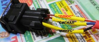
The device has three contacts - pulse, ground and voltage. At the same time, car owners have three verification methods at their disposal.
First option:
- Removing the speed sensor from the car.
- Move the multimeter to the voltage change position (Volts).
- Determining the purpose of the contacts (pinout).
- Search for the pin that receives the pulse signal.
- Connect the “plus” of the multimeter to this terminal. “Minus” is connected to the ground terminal (you can use the car body).
- Rotate the shaft and monitor the voltmeter readings. The higher the cranking speed, the higher the voltage level.
To simplify the rotation process, a small piece of tube (for example, vinyl insulation) is put on the speed sensor axis.
The second method (suitable for Hall effect sensors) without removal:
- Check that the controller is connected.
- Lifting one wheel of the car. The goal is to lift it off the surface for easy rotation.
- Preparing the multimeter - switching the scale to measure voltage.
- Connecting the probes to the contacts in the same way as described above.
- Rotation of a wheel disconnected from the surface and evaluation of the results obtained.
The voltage level and frequency must change. This indicates that the speed sensor is working properly. If the readings remain unchanged, the device has failed.
The third method is with a control lamp:
- Preparing the warning lamp and turning on the ignition.
- Raising the car wheel for further rotation.
- Connecting one wire to the battery positive, and the second to the signal contact of the DC;
- Spin the wheel and watch the light bulb.
If the lamp blinks noticeably when the wheel rotates, this indicates that the speed sensor is working properly.
The fourth method is with a warning lamp and removing the speed sensor:
- Remove the controller from its original location.
- Build the circuit shown below.
- Connect the wires to the pins according to the pinout below.
- We connect one terminal to ground, the second to the battery positive. The latter can be not only for a car - you can use any 12 V power source.
- Take a piece of brake pipe and place it on the sensor rod. To make it easier to control the number of revolutions, screw electrical tape onto the tube, as shown below.
- Start rotating the rod using the tube. As a rule, the light should blink 6 times in one revolution, but it all depends on the make of the car.
Automatic transmission check
In cars with automatic transmission, it is better to trust the professionals. The reason is that such cars have many electronic components that are closely interconnected with each other (directly or through the ECU).
An attempt to independently check the speed sensor can lead to even greater damage and breakdown of the automatic transmission system.
There are many cases where attempts at self-checking ended in expensive repairs or the need to sell the car.
Before checking
Before you start checking the speed sensor, you need to perform several mandatory steps.
- In most cases, the cause of the malfunction is an open circuit. To eliminate this possibility, check if it is intact. To do this, disconnect the power and examine the circuit for contamination, oxidation and other unwanted elements. If they are found, clean the contacts and apply a protective substance to them - for example, Litol.
- Often the wires located next to the plug are damaged. This place bears the most serious load - as a result of constant bending, the integrity of the lines is disrupted. Check out this place.
- As an additional measure, it is recommended to measure the resistance in the ground circuit. It should be 1 ohm; other indicators indicate a malfunction of this part of the system.
This is interesting: Chinese IT giant is developing computer-controlled cars
Description of how the speed sensor works on VAZ cars
Unable to find faults? So the problem is in the sensor itself. It is necessary to perform a set of diagnostic measures to analyze it.
Checking the drive
Sometimes you only need to check the DC drive. Algorithm of actions:
- Raising one wheel using a jack.
- Search for the speed sensor drive (it is easy to find, thanks to its “sticking out” from the gearbox).
- Rotate the wheel with your free foot.
It is easy to determine by tactile sensations whether the drive is working or not. If the device does not function, it is worth disassembling it and assessing the condition of the teeth on the gears. If you lack experience, it is better to entrust the work to a specialist.
Checking the crankshaft sensor with a multimeter
The crankshaft position sensor is one of the most important sensors without which your car simply will not start or driving will be impossible. The main task of this device is to ensure synchronization between the fuel supply and the moment the spark ignites on the candles.
So, you suspect a faulty DPKV. First of all, you need to find information on the resistance of this sensor for your car. After this, remove the sensor and remember its position using the special marks. Visually assess the condition of the working part of the sensor. It must be clean and without mechanical damage. If there are any, then there may be no point in further actions and the sensor simply needs to be replaced.
Checking the crankshaft sensor
After a visual inspection, measure the resistance with a tester. To do this, connect it to the working contacts of the sensor and take readings. If the DPKV is working properly, the device screen will display values from 550 to 750 Ohms. We strongly recommend that you find out what values are normal for your car.
Checking the crankshaft sensor
Checking induction DC and with reed switch
Note that speed controllers differ in the signal coming from the wheels. Taking this fact into account, the DS check is also built:
- WITH REED SWITCH. The signals are rectangular in shape. The cycle is from 40 to 60 percent. Switching occurs at a voltage from 0 to 5 Volts or when the battery voltage is reached.
- INDUCTION. With these speed sensors, the signal is in the form of waves, so the voltage changes based on the speed at which the wheel spins. This can be seen on the oscilloscope. Otherwise the principle is identical to what happens on the crankshaft angle controller.
How to check induction DC?
First, we check for the presence of grounding and 12 V voltage in the contacts. Such contacts are checked by dialing. And the contact of the pulse signals is checked during torsion.
The voltage between the output and the ground of the working speed sensor ranges from 0.5 V to 10 V.
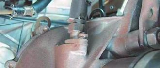
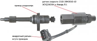
This is what the speed sensor drive looks like in a car
It is also easy to check the sensor drive with your own hands. We do everything in this sequence:
- Use a jack to lift one of the front wheels.
- We find where the speed sensor is located and wrap our fingers around it.
- Use your foot or, if you have an assistant, to rotate the raised wheel.
- The fingers on the sensor will feel an impulse if the DSA is working.
The voltage of such a sensor varies with wheel speed, as with the steering angle sensor. From the rotation of the wheels, the signal begins to be transmitted, so this operating principle is similar to oscillations of a wave pulse.
Sensors whose operating principle is not related to the Hall effect are checked using a multimeter:
- diagnostics of DSA with reed switches is carried out by monitoring the voltage, the value of which should be in the range of 0–5 V (or from zero to the operating voltage of the battery);
- For induction type sensors, voltage is also controlled. To do this, you will have to remove it, connect a multimeter and check the readings of the device by bringing any metal object to the DSA. If the voltage does not change, the device is faulty.
The solution to the problem with a faulty device is solved simply by replacing it. But, if the test results show that the sensor is working, you should perform a few more steps. That is, lift the wheel again and, rotating it, check the operation of the DSA drive. If this part does not rotate, it is disassembled and damaged parts are replaced - most likely gears.
Speed sensor test video
DETAILS: TPS throttle position sensors in Priora and Kalina sensor characteristics
Replacement instructions
If the malfunction is confirmed and the sensor needs to be replaced, the work is done according to the following algorithm:
- Turn off the ignition, open the hood and remove the terminal from the battery.
- Search for speed sensor. It can be located in different places, it all depends on the car model. This information can be found in the service book.
- Cleaning from contaminants. This is necessary to avoid foreign elements getting into the transmission.
- Removing the power connector and unscrewing the device. If you cannot disconnect the controller, you should treat the connection location with WD-40. It is not recommended to apply excessive force, as this may lead to damage to the integrity of the case. After applying the specified liquid, you need to wait some time.
- Removing the old and installing a new sensor, connecting wires.
- Resetting errors on the ECU (for models that have an electronic unit). If this work is not done, the light on the dashboard will light up, and the ECU will send signals about a breakdown.
Subtleties of checking for different car models
Depending on the vehicle, the location, malfunctions and details of the check may vary.
VAZ-2110
A common malfunction on the “ten” is incorrect operation of the odometer, expressed in incorrect speed data. The cause may be a broken speed sensor or drive.
Sometimes the malfunction is due to oxidation of the connectors or damage to the wiring.
The sensor is located near the collector, so the cause of the breakdown may be damage to the wiring due to high temperature.
To check the performance of the product, you can use one of the three methods discussed above.
If the device is faulty, replacement will require a 21 or 22 key. When purchasing a new speed sensor, it is recommended to choose a product with a metal rod. It lasts longer and is more reliable.
Kalina
As with other models, a popular reason for DC failure is damage to the wiring (oxidation, rust, poor contact, melting wires, etc.). A multimeter is used for control.
The probes are connected to the central contact (“plus”) and to the body (“minus”). When vibrations occur, the voltage should vary from 0.5 to 10 V.
You can check the operation in other ways - by hanging the wheel or using a test lamp.
The location of the Lada Kalina DS is shown below.
Priora
There are a number of features in checking the Lada Priora speed sensor. Often a problem with it is indicated by error P0501.
Algorithm of actions:
- Inspection of the controller.
- Checking the quality of grounding at the contact connection.
- Reference voltage measurement. The Priora speed sensor has wires of different colors. It is located behind the collector.
Brown has a minus sign and pink has a plus sign. The signal wire is made in gray color. Using a multimeter set to voltage measurement mode, you need to check the reference U. The optimal value is from 12 V. If there is no voltage or it is less than the set parameter, you need to charge the battery and look for a breakdown elsewhere (ECU or power supply circuit). - Checking the quality of connector connections using a thin needle or plate. It is important that the contact groups do not fall out of the connector.
- Checking the speed sensor using an oscilloscope (the wheel must rotate at a speed of more than 5 km/h).
Before checking the DC, it must be removed from the vehicle, but the wires must not be disconnected.
Next, turn on the ignition and check the output voltage. To do this, you need to slowly change the rotation speed of the axis. The curve should have a voltage of five to one volt in the reverse direction.
If the voltage remains unchanged, this indicates a breakdown. An additional sign of failure is the engine stopping when changing gears, failure of the electric power steering.
To check the speed sensor, you can use a simulator - a device that changes the pulse frequency by pressing plus or minus. Using the product you can also check the machine's ECU.
Gazelle
To check the Gazelle speed sensor, you need to take the following steps:
- Unscrew the screws that secure the hatch near the gearshift knob.
- Remove and unscrew the DS chip.
- Check the operation of the device, starting with checking the grounding on the third contact. The first contact should have a voltage of +12 V. The black wire is “negative”, the yellow wire is “positive”. Green goes to the DS and instrument panel.
It is worth considering that the “positive” signal is sent to the DS and the reverse signal. If the reversing lights turn on after moving the gearshift knob to the appropriate position, there is no need to check the fuses.
Nissan
Nissan uses two input signals from the automatic transmission control unit - from the speed sensor and the vehicle speed sensor.
The first determines the rotation speed of the secondary shaft and sends information to the unit, and the second is used as an additional controller. It sends data when the master node is faulty.
The Nissan speed sensor is built into the speedometer assembly and plays the role of an additional device. Symptoms of a malfunction are dropping into neutral or illogical gear shifting.
The sensor itself is located behind the left fender liner, and to replace it you need to remove the left plastic protection (using the example of a Nissan Liberty).
If error “2” appears, you need to check the DC chain, the integrity of the wires and connectors. Studying the operation of the controller itself is carried out according to the standard scheme:
- removing the speed sensor (VSS) from the transmission housing;
- connecting a voltmeter to the terminals and switching the multimeter to AC mode;
- rotation of the drive gear (there should be a voltage with an amplitude of about 0.5 V);
- If there is no U, the sensor needs to be changed.
If tension is present, you need to look for another reason.
To replace the DS you need:
- put the car on a jack;
- discard the wiring from the sensor;
- unscrew the coupling bolt, loosen the clamp and remove the device from the transmission;
- check the condition of the o-ring (if necessary, replace it);
- Put the product in the reverse order.
Niva
The Niva's speed sensor is located on the transfer case. It is made in a plastic case, and inside there is an electronic part.
The device is highly fragile, so you need to be careful.
Check procedure:
- disconnecting the sensor;
- connecting the red (“positive”) probe to the product contact;
- connecting the minus to ground;
- fixing the tube on the shaft for rotation;
- switching the device to voltage measurement mode;
- shaft rotation and U control (this parameter must be changed).
To replace, you need to disconnect the terminals from the battery, press the plastic lock and use a wrench to unscrew the sensor (to simplify the work, you can use WD-40.
VAZ 21093 injector
The VAZ 21093 injector speed sensor is located on the speedometer drive mechanism (at the gearbox). To find it, just open the hood and remove the adsorber.
Performing the last step is not necessary, but it is easier to get to the desired point in another way. On the right CV joint side there is a wire that goes to the gearbox. It connects to the connector of the desired sensor.
In the case of injection VAZ-2109, the main sign of a speed sensor failure is the engine stopping at idle or when the clutch is pressed.
Also, a light on the dashboard lights up asking you to check the engine (code 24). For control, one of the three methods discussed earlier is used.
Speed sensor does not work: signs of malfunction and check
A vehicle speed sensor (VS) is necessary to measure the speed of a vehicle. The readings from the sensor are transmitted to the electronic control unit (ECU), which controls the engine and adjusts engine operation. On the vast majority of cars, the speed sensor is located directly on the gearbox, closer to the speedometer drive mechanism.
Among the main malfunctions of the DSA are: open circuits, damage or oxidation of contacts, failure of the sensor itself, malfunction of the speed sensor drive. If malfunctions occur, the speed sensor is checked with and without dismantling:
- multimeter (measuring signals within the operating cycle);
- using a control lamp;
Detailed information about the signs of a malfunctioning speed sensor, as well as how to check it, is presented in our article.
Speed sensor on a car: where is it located?
The speed sensor is located on the gearbox, in the area of the speedometer drive mechanism. The main task of the vehicle speed sensor (VS) is to measure speed, after which this information is transmitted to the ECU.
Having received a signal from the DSA, the electronic unit regulates the idle speed, controls the amount of air entering the engine, and also changes a number of other parameters. The faster the car moves, the higher the frequency of the signals transmitted from the speed sensor.
How DSA works
The operation of the speed sensor is based on the Hall effect. The pulse-frequency signal generated by the sensor, which is transmitted to the ECU, is directly proportional to the speed at which the car’s wheels rotate.
Next, the engine control unit “calculates” the interval between pulses, determining the speed of the car.
The speed sensor has failed: signs of a malfunction
An obvious sign of problems with the DSA is a non-functioning speedometer. If a fuel-injected engine stalls at idle or during transient operation, the vehicle speed sensor may also be the cause.
In cases where the speed sensor (speedometer sensor) is completely out of order or transmits incorrect data, the power unit operates extremely unstable.
If such malfunctions occur in the motor, you should pay attention to signs of a malfunction of the speed sensor, and it is also necessary to check the speed sensor (can be done by yourself).
At the initial stage, it is important to determine that the speed sensor is not working and the cause of engine malfunction is a breakdown of the DSA. You should pay attention to the following signs of a malfunctioning speedometer sensor:
- in XX mode the engine is unstable;
- when the vehicle is moving, the speedometer does not work or the readings are incorrect;
- traction is lost, engine power is greatly reduced;
- the car accelerates jerkily, dips are noticeable during acceleration;
- When you release the gas pedal after accelerating the car, jerks are observed;
- fuel consumption is greatly increased
Also, “check” should usually light up on the instrument panel, and the error is recorded in the ECU memory in the form of a corresponding code. Please note that on some cars the “check” may not light up. There have also been cases when the car’s BC conducts self-diagnosis and displays the error “no DSA signal.”
The speedometer sensor does not work: reasons
DSA malfunctions are usually caused by open circuits, damaged or oxidized contacts.
Structurally, the car speed sensor itself is quite reliable (considering the speed sensor, the device circuit is quite simple).
It is also important to consider the fact where the speed sensor is located. The location in the engine compartment at the gearbox does not prevent oil contamination, ingress of technical fluids, water and dirt, etc.
- At the initial stage, it is necessary to check the wiring and contacts for integrity. As for the contacts, it is necessary to clean and lubricate them (Litol type lubricant is suitable);
- The wires to the speed sensor usually break near the plug at the bend, as the wiring frays and the insulation cracks;
- At the same time, it is recommended to check the resistance in the grounding circuit. The norm is 1 Ohm.
If no wiring or contact defects are found or the methods discussed above do not resolve the problem, you need to check the speed sensor for functionality.
How to check the speed sensor yourself
Among the main ways to check DSA are:
- checking with a voltmeter;
- diagnostics using a control lamp;
Many cars have a sensor whose operation is based on the Hall effect. It is not difficult to check this type of DSA. However, there are other types of speed sensors: reed sensor, as well as inductive speed sensor. The method for testing such sensors is somewhat different.
Checking the speed sensor with a multimeter
The most common type of speed sensor has 3 contacts: pulse, ground and voltage. First of all, you need to determine the presence of grounding and 12V voltage on the contacts.
These contacts are checked with a multimeter, while the “pulse” contact is checked by rotating. Normally, the voltage between the pin and ground should be from 0.5V to 10V.
To check the speed sensor with a voltmeter you will need:
- remove the speed sensor;
- determine the purpose of contacts;
- switch the multimeter to voltmeter mode;
- connect the incoming contact to the output;
- ground the second contact to the engine (can be to the car body);
Then the speed sensor must be rotated, determining the presence or absence of signals in the work cycle. The output voltage of the sensor is also measured. To do this, it is recommended to put a piece of tube on the sensor axis and rotate it at a low speed of up to 5 km/h. The faster the sensor rotates, the higher the voltage on the voltmeter should be.
How to check the speedometer sensor without removing it
If the owner does not know how to remove the speed sensor from the car or intends to do a quick check, you can do without removing the sensor. For such a check you will need:
- raise the car on a jack so that one drive wheel comes off the ground and rotates freely;
- Next, the sensor contacts are connected to a voltmeter. Then you need to rotate the wheel and determine whether voltage appears, and whether there is a change in frequency;
If the voltage is fixed and the frequency changes, the speed sensor is working. In the case when there is no voltage, there is a high probability of failure of this element.
Quick check of the speedometer sensor with a test light
Checking the speed sensor can also be done using a warning light (or so-called control light). As part of such a check:
- The pulse wire is disconnected from the sensor;
- the car is lifted on a jack;
- one wheel is hung out and the ignition is turned on;
- then one control wire is powered to the “+” battery;
- the second wire will be connected to the “signal” connector;
If the light blinks while the wheel is rotating, the speed sensor is working. If the lamp does not blink, it will indicate that the sensor is faulty and requires replacement.
How to check the speed sensor drive
In some cases, the cause of the malfunction may also be not the sensor itself, but its drive. For this reason, it is also recommended to check the speedometer sensor drive. For such a check you will need:
- jack up the car and hang out the wheel;
- detect the sensor drive coming out of the gearbox;
- rotate the wheel (you can use your foot yourself or have an assistant);
While the wheel is rotating, you need to tactilely evaluate the quality of the drive (feel it with your fingers). It is important not only to make sure that the drive works, but also how stable its overall operation is.
As a rule, any deviations from the norm are grounds for disassembling the drive. Often the teeth on the speed sensor drive gears are damaged.
Other types of speed sensors: reed switch type and induction type sensor
Although such sensors are used much less frequently than Hall effect sensors, such solutions are found on some cars. For this reason, it is necessary to take into account some features.
- A sensor with a reed switch produces signals in the form of rectangular pulses with a cycle of 40-60%, while switching is carried out from 0 to 5V or from 0 to battery voltage 12V.
- As for the induction sensor, the signal from the rotation of the wheels is similar to a wave oscillation (wave impulse). As a result, the voltage changes based on the rotation speed. The principle itself is similar to the operation of the crankshaft angle sensor.