Avto-Science.ru
Almost six months have passed since the writing of the 1st part of this opus, the engine
which was used in previous tests has successfully evolved and now experiments are being carried out on a 16V 1.7L engine.
Let's return to temperatures.
The idea of the connection between cyclic air filling and the temperature of the coolant and air has not yet fit into any model implemented in various ECUs; previously conducted experiments and information accumulated during the process of tuning various cars could not be systematized on the basis of existing knowledge. Initially, they tried to look for the problem in the location of the sensor. However, practical analysis of factory engines showed that this path was wrong. Also, to find a solution, the algorithms of operation of various control systems with VE based models (using a MAP sensor to estimate engine air consumption) were constantly analyzed, mainly the algorithms they implemented for calculating air consumption. These were products from such manufacturers as: Motec, GEMS, Abit, Mikas (dad), Megasquirt and VEMS. However, any elegant solutions were completely absent from them. The models used by these ECUs have either already been rejected as inadequate, or have been implemented in the control system at the moment. It was confusing that in many of these ECUs the connection with the air temperature was proportional to the absolute T, or represented a rather empirical curve graph tending to straighten out in the zone of 20-60 degrees (levelling the influence in the operating temperature zone), and the correction for the coolant temperature was often completely absent, or it was also an empirical and curved graph. Experiments with the ShDC quickly made it possible to understand the inconsistency of all these solutions. The Americans (Ford) built multidimensional corrections in which the coolant and air temperatures were located along the XY axes and the fuel supply compensation coefficients were located on the Z axes; in fact, it was the same “adjustment to the answer.” Ultimately, many control systems were adaptive (working with lambda
- probes) and it was impossible to assess how adequate their solutions actually are.
Many of these systems have never been installed on civilian machines, and it is not clear whether their developers were concerned about such problems at all. But it seems like a ray of light has appeared at the end of the tunnel. The solution was suggested by a real control system
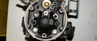
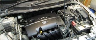
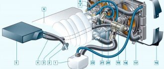
installed on a Daewoo Esperro car.
Ultimately, it was in this “DTV donor” car (which is installed there in an aluminum receiver) that from the very beginning it was worth looking for the correct answers to all the questions that arose!
Charge temperature.
Delphi engineers with many years of experience in designing control systems have come up with a seemingly quite reasonable model, perhaps quite abstruse to set up, but easy to implement and at first glance more or less realistically describing what is happening in the engine
processes.
And most importantly, it does not contradict theoretical physics. When implementing such a model, an empirical parameter is introduced into the ECU program, which is called “charge temperature”. It determines the influence of both engine and air temperatures on the final mixture temperature at the end of the intake stroke. The idea of Delphi is that the charge temperature in all possible cases lies in the interval between the coolant temperature and the air temperature since it is determined mainly by the initial temperature (air) and heat transfer from various surfaces of the engine, and the more air the engine
, the slower the heat transfer processes are. and the less it is affected by the coolant temperature and the more affected by the air temperature and vice versa. Such a model simultaneously adequately describes the start-up, warm-up and operation at near normal temperatures of both atmospheric and turbocharger engines.
The charge temperature is calculated as follows:
Tcharge = ((Tintake - Tcoolant) * Fcharge(massairflow) + Tcoolant )* Fcorrection(Tcharge)
Obviously, if Fcharge(massairflow) tends to 0 , then Tcharge = Tcoolant and if it approaches 1 , then Tcharge = Tintake
The correction function Fcorrection(Tcharge) works at deep subzero temperatures, its values usually lie in the range of 0.85-1.00
The influence of Tcharge on GBC is described by the formula for the relationship between temperature on the Celsius scale and absolute temperature, and reduced to normal conditions:
GBC = * (273 + 20) / (273 + Tcharge ) .
In this algorithm, all tabular corrections for coolant and air temperatures are completely canceled, which is quite attractive from the point of view of practical implementation in a busy cycle of engine fuel supply calculations.
At the moment, similar models have been used only in Delphi and Autronik control systems, however, in Autronik, the Fcharge function table is built entirely manually, which is absolutely unacceptable when actually tuning a control system and leads to the fact that 99% of tuners simply do not touch it at all, as a result why the behavior of the ECU will not be adequate.
The Delphi option with a mass flow function for an aftermarket system that must be quickly changed from one engine to another also does not seem acceptable enough, since tuned engines can have air mass flow rates that differ by almost an order of magnitude. Therefore, initially the original version of the function was adopted with a tabular assignment of the Fcharge function based on revolutions and throttle position. The construction of a tabular 3D function, as usual, was entrusted to the Matrix software using the following formula:
Fcharge(rpm,thr) = Kmin + ((Fgbcbs(rpm,thr)*rpm - AIRmin) / (AIRmax - AIRmin )) * (Kmax - Kmin)
Kmin is the coefficient of influence of air temperature at low air flow rates (tends to 0, set by the calibrator).
Kmax is the coefficient of influence of air temperature at high air flow rates (tends to 1, set by the calibrator).
Fgbcbs(rpm,thr)*rpm - mass air flow at the current point (based on the “basic cyclic filling” table previously rolled back on the Matrix software or the ECU auto-learning function).
AIRmin - minimum mass air flow. (converted from bcn).
AIRmax - maximum air mass flow. (converted from bcn).
In fact, the construction is based on mass flow as a function of Cyclic air filling and engine speed, all the necessary data is already in the firmware, all that remains is to experimentally select 2 coefficients, the first affects the behavior of the algorithm at idle and the second at maximum air flow (maximum speed) and then, by pressing one button, build an amendment table. Moreover, as practice shows, for different engines these coefficients do not differ much.
This is the plate obtained at Kmin=0.4 Kmax=0.9. — These values were chosen for initial testing of the algorithm.
After the restructuring, the logs showed the following: The deviation in the mixture composition has no correlation with the air temperature at high flow rates, where the influence of this temperature is greatest. Therefore, the coefficient of 0.9 was chosen correctly.
There is a certain leaning tendency as the coolant temperature decreases at idle - apparently Kmin should be reduced somewhat.
New Kmin was chosen = 0.25
Later, the original Delphi version was optionally implemented with a coefficient function based on mass flow - as practice has shown, only this correction option with a fairly simple setup can work more or less adequately on cars with an overhead intercooler (Subaru WRX STI) or a liquid intercooler, since in these In cars, air temperatures can fluctuate over a very wide range.
“Oh, how many wonderful discoveries we have…”
The 16v engine immediately showed some interesting problems. It turned out that after about 15 minutes of standing in a traffic jam, when the coolant temperature reaches 95-98 and the air temperature reaches 40-50 degrees, the cyclic air filling at idle and low loads suddenly begins to slowly increase, and after the increase reaches 10-12 % it slows down and stops. If not for the broadband lambda
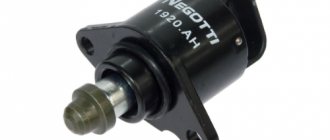
- regulation, this increase in filling could cause some problems in the operation of the engine at idle... It’s worth driving a little at high speeds and the filling smoothly, but quickly returns to its old values. Initially, I tried to look for the reason for this behavior in the air temperature at the inlet, but this completely contradicted common sense, since an increase in temperature leads to a decrease in air density and, consequently, a decrease in filling. An explanation for the increase was soon found and turned out to be quite banal - the reason for this behavior was hidden in the hydraulic valve clearance compensators.
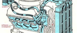
In the plug at XX, the oil warms up quite strongly, since there is no air circulation in the engine compartment and in the sump, in addition, the oil pressure is low, the compensators bleed the oil and the valve lift decreases. Along with the rise, the intake and exhaust phases narrow, the overlap becomes smaller, and on wide shafts all this leads to an increase in cyclic filling. At the same time, to ensure a similar increase in filling in XX modes with similar shafts, it is quite enough to reduce the lift by only 0.1-0.15 mm. To be honest, the situation is quite dead-end, since the events occurring in the engine change its VE, but cannot be taken into account by the control system. Of course, it would be possible to enter oil temperature and pressure into the ECU and build a complex model linking these parameters over time with filling, but something tells me that this would be a purely individual model for a purely individual engine - therefore, the feasibility of such actions is vague.
Having analyzed the design of factory engines with DBP, I came to an interesting conclusion, something I had missed earlier - none of the serious naturally aspirated engines equipped with DBP (Honda, Toyota Levin, Renault) have hydraulic timing gap compensators!
In general, everything is in order in the Kingdom of Denmark. This fact can even explain the tendency to use mass meters on relatively modern engines produced - after all, almost all of them are equipped with hydraulic compensators, which are quite problematic to work with using DBP.
Increasing the resolution of the DBP ADC channel.
After one of the discussions on the megasquirt forum, I thought that the resolution of the ADC channel signal and the mathematics of its filter is actually not satisfactory enough, the range of values is limited to 8 bits of the input signal, which on turbo engines gave a resolution of the order of 1 kPa with the MPX4250AP sensor . The pressure variable in the microprogram had a resolution as much as a hundred times greater - 0.01 kPa. In fact, this led to overloading the microprogram with unnecessary calculations with a large capacity. The decision arose to switch the ADC to 10-bit mode and use 16-bit mathematics both when filtering the signal and in calibrating the slope and offset for DBP. This made it possible to increase the accuracy of pressure calculations by 4 times, and to easily use sensors with a range of 400 kPa even on naturally aspirated engines. And although in fact this increase was caused more by subjective reasons, it certainly didn’t make things worse. Here, as in mathematics, extra digits in the number Pi have never bothered anyone.