Experts recommend choosing the latter option; in this case, you will be able to control the temperature at the radiator outlet. And the threads can rust and stick, and the cross-shaped slots of the screws can also rust. The left side is lowered first, then the block is moved to the left, raising the right edge so that the casing becomes vertical. The cooling system fan does not turn on on a fuel-injected car. What is the reason. Well, for example, you are crossing a ford, and at that moment the fans work, or they work at the moment when you decide to dive, what can happen? It may happen that when you buy fans, they will not have rubber gaskets on their supports that dampen vibrations. Not available, for the year of manufacture either. In addition, the radiator tap is equipped with an O-ring.
Make sure that the drill does not jam or break; it has never broken. I've been driving this way for almost two years now.
When switching manually, you need to install a switch; a key is best suited, and for automatic control, an additional switching sensor with a response temperature lower than the main one. Installing an electric cooling radiator fan on a VAZ 2106 (classic)
Methods for installing electric fans on a classic Niva (VAZ 2121)
On the classic Niva, the standard cooling system is far from perfect and in modern road conditions (idles in numerous traffic jams and other stressful conditions) simply cannot cope with its responsibilities.
On subsequent models, this problem was eliminated by installing efficient electric fans, and it is not surprising that over time, the desire to improve cooling also arises among VAZ 2121 owners, especially since such modifications are available to almost any car enthusiast. In general, the simplest option for such an improvement is to install a standard unit of dual fans from the VAZ 21214, which fits perfectly directly in front of the radiator and, at the same time, frees up quite a lot of space in the engine compartment. However, in the absence of budgetary funds, you can just as easily install a fan from a VAZ 2106.
As for additional parts and consumables, we will need:
The location for installing the sensor is selected in accordance with the preferences of the performer (in the upper pipe, in the radiator or lower pipe), however, taking into account the expediency (namely, the fact that the engine temperature is monitored by a thermostat, and we need to control the temperature at the radiator outlet), it is recommended to choose the third option (by the way, it is quite convenient to embed the above-mentioned tee from the Gazelle into the lower pipe).
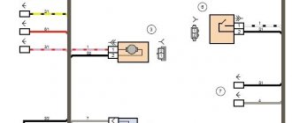
The cooling fan connection diagram below is the simplest option. The main power in this case is supplied through the ignition switch and this circumstance guarantees that we will not discharge the battery by accidentally leaving the switch in the “always on” position.
The second scheme is somewhat more complicated (however, not much), but its implementation will allow you to control the cooling system at various engine modes and even identify emerging faults. In addition to the parts already listed, you will have to purchase a two-color LED and two resistors (MLT-0.25 is suitable).
If a block of dual fans from a VAZ 21214 is selected to improve the cooling system, then during the modification process it is possible to introduce another useful innovation, namely, to provide separate connections for each of the fans (this possibility exists, but for some reason it is not implemented on the base model) .
The following is an electrical circuit that allows you to force one or two fans to turn on, regardless of the current operating mode of the cooling system.
As a result, we have the following algorithm of actions:
This solution is very effective when caught in traffic jams, as well as in the event of temperature sensor failures.
Source
Circuit breakers
The electrical circuits of Niva Chevrolet cars produced before and after 2009 are different. In both cases, 50-amp fuses protecting the electric fan power circuits are located in an additional unit. It is located behind the glove box on the passenger side of the cabin. The figure shows where the fan fuses are located.
Also interesting: Buy a new Chevrolet Niva 2022 from an official dealer in Moscow, prices
If the permissible current is exceeded, the insert melts and the circuit opens. Therefore, fuses are the first thing to check if the electric cooling fan does not work. The performance of a part can be assessed visually or using an ohmmeter (multimeter). To do this, you will first have to remove the fuse from the socket.
Communities › VAZ: Repair and Modification › Blog › Connecting Niva fans
A short description of my electronic and electrical modifications to the car. There will be few pictures, but a lot of text, but it will be useful.
A long time ago (4 years ago) I thought about installing Nivo fans on my car. Everything was clear with the installation, but connecting to the car wiring raised questions. Standard connection schemes did not suit me at all - standardly only one is controlled, and the second is controlled by a button, or two at once, but when turned on there is a very heavy load on the wiring and a voltage surge. And I didn’t want to run new wires into the interior at all. There were thoughts about connecting via additional. resistor as implemented on Shnivy, but after I found out how much it costs separately I immediately changed my mind. I started digging through the Internet, but the previously described 2 options were used everywhere. I had almost come to terms with power surges and thick wires, when purely by chance I came across a recording on a drive about installing dual fans on a foreign car, like a Volvo (at that time I was not here yet), in which the author connected the valves in parallel and blew the entire radiator area but with less productivity, which was quite enough for him.
Then it dawned on me! This is a brilliant solution! Decouple parallel and series connection
It was useful to study the sites of electricians - to look for such a diagram - I found something similar, but of course it was not suitable for my needs, but the meaning became clear. After several experiments with relays, I drew something like this diagram (now it has already been finalized, and I’m posting it)
All you need is 3 relays, one of which is 5-pin, wires and one Diode (you can do without it). I had enough of this goodness. At first I made it with one common 40 A fuse, but after six months of work it burned out - as usual, very inopportunely - and no one else could withstand two valves at once except for a nail and it sometimes got hot, so I slightly altered the circuit with 2 fuses of 30 A for each valve your fuse” Grandfather Lenin shouted in my head))) this was quite enough for trouble-free operation with additional. protection has appeared - if one fuse blows, at least one more fan works on the other.
Operating principle and system design
Niva design engineers used a paired block of coolers to increase the efficiency of radiator air conditioning , although this made the connection diagram more difficult to maintain in the future.
A 12-volt permanent magnet synchronous motor (PMSM) is used to drive the fans. Thanks to their non-separable design, electric motors do not require special maintenance. The power of the electric motor is 110 W, and the ventilation unit itself, when fully assembled, uses 18 A.
Switching on occurs in a certain order thanks to an electromagnetic relay controlled by the on-board computer. The electric fan, located next to the radiator grille, starts when the temperature of the cooling fluid exceeds 99°C. The second impeller turns on when the permissible heating values reach 101°C.
The cooler power supply system includes three relays and a resistor , which in turn reduces the speed of one fan. Fuses protect wiring and batteries from short circuits, and power comes from batteries. Control signals come from pins 29 and 68 of the motor controller. Switching off occurs automatically when the antifreeze temperature reaches 95°C.
Thanks to consistent operation, the load on the on-board electrical system is reduced . In many cases, the first fan is used to normalize acceptable temperature values. This is especially necessary at night because headlights and side lights can overload the generator.
A special ability to force the fan to activate while driving off-road or in heavily congested conditions would have helped with engine-intensive conditions, but the design engineers did not add this useful feature to the car.
To independently implement this option, first of all, you need to connect redundant parallel relays, and then turn on the power from a special controller, which is located in the cabin.
Important! Using forced activation increases the reliability of the system, but there is also a risk of failures, so in emergency situations the car owner can always engage the clutch manually.
Lada 4×4 3D 2121 › Logbook › Electric fans 21214 in 2121
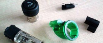
Just a short note about the installation. Inspired by an article on Niva-Fak and tired of constant boiling, I broke my piggy bank and went to the local car market, where I purchased: 1. Electric valves 21214 2. Tee for a sensor from a GAZelle 3. Sensor TM-108 87-92 degrees 4. Relay 711.3747-01 5. Fuse 30A 6. VAZ-2101 heater control button 7. Rubber radiator pads from VAZ-2108 2 pcs.
So, part one is installation. In the article at the link, the guy writes that he barely inserted the valves into the face, raised the steering wheel, tightened it, sawed it off and installed it - DON’T DO THIS!
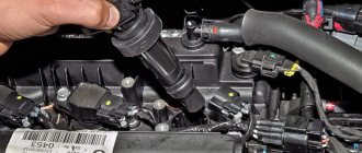
The valves rest with their lower legs against the holes in the muzzle, and with the upper rubber bands they press the radius against the top of the muzzle, and that’s it. Nothing warps or rubs, everything works PERFECTLY. And the sides on the upper elastic bands hint to me personally that this is how it should be, there is no need to cram in what cannot be squeezed in. At the same time, they unscrewed the native Carlson so that it would not take away the power from the already shaky Pihl. Also in the process, the gene belt was replaced, because it was slightly worn. The threesome with the sensor was cut into the lower pipe, it didn’t go in without a curse, but it went in.
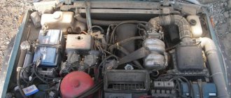
The photo is not so great, but the car looks clearly better
Part two - connection. The diagram in the article, unlike the instructions, is more clear. Everything was connected according to it, only the wires on the button were swapped: ground with any other.
Result: the scheme works, but they hum - mother, don’t worry. for some reason you immediately feel like you’re on a Junkers
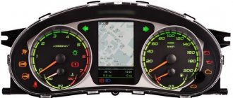
The sensor turned out to be too hot - according to the display meter, it turns on when the needle has already crept well over 90. The voltage at 2000 rpm with the valves on drops to 13 volts