Parktronic (parking radar) is a convenient and practical solution that greatly facilitates the operation of the car. Parking sensors are especially necessary in a metropolitan area, where parking a car is frequent and can be very difficult.
It would seem that rear view cameras should have forced all types of parking sensors out of the market, but this did not happen. First, a high-quality camera is noticeably more expensive and also gets dirty. Secondly, the camera requires a separate display or a radio with a monitor, which complicates the installation itself and requires more work.
At the same time, unlike the rear view camera, the parking sensors allow you to navigate well in the dark and capture even small objects that may not be visible in the mirrors or on the camera. Also, parking sensors can be used in conjunction with a camera. Next, we will look at how to install parking sensors on a car with your own hands.
Operating principle and types of parking sensors
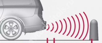
The principle of operation of the parking sensors is that the electronic unit processes signals received from wireless transceiver sensors installed on the car’s bumper and presents them on the display in a form convenient for the driver.
In the simplest parking sensors, the information is an intermittent sound signal, the frequency of which increases as the vehicle approaches an obstacle.
In the most common parking sensors, information with an audible signal is supplemented by a monitor or display, on which the distance to the obstacle in meters is displayed in graphical or graphical and digital form. You can see the structural wiring diagram of such a radar in the photograph. Expensive models of parking sensors additionally have a video camera, the lens of which has to be constantly wiped clean of dirt, which in practice negates all its advantages.
Distance measurement sensors in parking sensors are used in two types - tape and ultrasonic. Tape sensors are a metal strip attached to the inside of the bumper; they detect an obstacle only at a distance of less than 30 cm and do not work well in a wet environment, so they are practically not used.
There are types of wireless parking radars in which the signal from the electronic unit to the monitor is transmitted using a radio signal. The price of such parking sensors is an order of magnitude higher, and the apparent ease of installation is deceptive, since it is still necessary to supply the supply voltage to the devices using wires, which practically negates the advertised advantage. In addition, such a system is susceptible to radio interference, which reduces the stability of the forging radar as a whole. I immediately refused to buy such parking sensors.
Design and principle of operation of an ultrasonic parking sensor
Ultrasonic parking sensors are unpretentious and can confidently detect any obstacle located at a distance from the car closer than 2 meters. The ultrasonic sensor is similar to a telephone headset, only the speaker and microphone are installed in the same housing.
The sensor works as follows. A burst of pulses with a frequency of 40 kHz is periodically supplied from the electronic unit to the sensor emitter. If an obstacle is encountered along the path of the pulse, it is reflected and picked up by the microphone. It is then transmitted to an electronic signal processing unit, which measures the time interval between the moment the pulse is emitted and the time it returns from the obstacle. The further away the obstacle is, the longer it takes for the signal to return to the sensor. The distance is determined in this simple way. The electronic unit can only convert the travel time of the pulse into meters and display the information on the display.
The distance at which the parking sensor can detect an obstacle depends on the power of the emitted pulse and the sensitivity of the microphone.
The angle of radiation of the pulses is limited, therefore, to completely cover the blind spot, at least four ultrasonic sensors must be installed on the bumper.
How to connect the device
To connect parking sensors to 4 sensors, you need to route the cables from the ultrasonic elements to the control controller, and then connect the information display. The control unit requires power supply only when reverse gear is activated. Installation of equipment for 8 sensors differs in the installation of an additional cable braid from the sensors located in the front bumper. The controller is attached to the wall of the luggage compartment using screws or plastic clamps; the device can be mounted under decorative trims.
For example, the schematic diagram for connecting the SPARK-4F assistant controller provides for the input of cables from the sensors; a positive power signal is supplied from the reverse gear lamp. This technique ensures that the equipment operates only when the vehicle is in reverse. The negative wire is attached to special bolts welded to the body. The control unit has a block for switching direction indicator lamps; the signals are used to enter the programming mode and switch menu sections.
The parking sensor circuit involves activating a quiet mode, which allows you to determine the distance to cars standing behind or in front. The controller is additionally connected to a limit switch located in the brake pedal. It is allowed to supply power from the brake lamps located in the rear lights. When you press the pedal and the gear selector is in neutral, the display shows the distance to obstacles. The display design includes a button to force the display to turn off.
Some assistants support the function of warning the driver about cars in blind spots. The sensors turn on when a warning signal is given by the turn signal; when a car or motorcycle is detected, the warning LED on the pillar trim turns on, and the signal is duplicated on the display. It is possible to permanently or temporarily disable the function by sending a signal to a separate contact (performed with a toggle switch or by pressing the brake pedal).
Selecting parking sensors
Heated mirrors: benefits, design and installation yourself
When choosing and purchasing an ultrasonic parking sensor, you must pay attention to the instructions. The presence of a translation into the language of the country in which the device is sold is a kind of guarantee of its quality
It is also necessary to ensure that the warranty is properly issued. At the same time, you need to keep in mind that the warranty is only valid if the device is professionally installed.
Self-installation requires a detailed study of the technical features of parking sensors: installation height, sensitivity and range of sensors. In addition, for adequate operation of ultrasonic sensors, parking sensors must be connected to the on-board computer strictly according to the diagram. The control unit of the device is located in a convenient place, for example, in the trunk. At the same time, the main thing is to ensure normal access to it and the impossibility of mechanical damage.
Installation of parking sensors
To install the system yourself, you will need the following tools and materials:
- drill with a drill or cutter of the required diameter;
- screwdriver;
- key;
- roulette;
- marker or pencil;
- insulating tape;
- double-sided adhesive tape (scotch tape);
- solvent.
Let's look at the installation process using the example of installing a classic device consisting of 6 sensors (2 on the front and 4 on the rear bumper). Taking into account the required installation height, the locations for placing the sensors in the bumper are marked. It is advisable to remove the bumper itself in order to see its design from the reverse side. Using a tape measure, the length of the bumper is measured and markings for future sensors are placed at an equal distance from the corners.
Places for installing sensors are drilled with a milling cutter. The sensors themselves must be installed without any deviations to the sides, otherwise the parking sensors will give unreliable signals.
On the inside of the bumper, the sensors are fixed using specially designed rings. The wires are secured with electrical tape to other electrical wires located in the bumper. After this, the bumper is installed in place and secured accordingly. The procedure for installing sensors on the front bumper is similar to that described above.
Observing the polarity, the control unit must be connected to the wires of the reversing lamps. The placement of the device display in the cabin depends on the driver’s preferences. To install it, you can use double-sided tape. The control unit can be secured in the same way. Before installation, it is advisable to degrease the selected area with a solvent. All wires in the cabin must be routed under the floor mats to avoid damage.
First of all, you need to check the range of the sensors, as well as their response to various obstacles.
The parking sensors are not working, what should I do?
There are many reasons why parking sensors may fail or not work after installation. Therefore, we will consider two cases:
New parking sensor doesn't work
At the beginning of the article, we recommended checking the functionality of the device before installing it on the car. If it worked before installation, you should check the connections of all main components. All components must be connected according to the instructions that come with the kit. Check whether you are properly powered by the reverse or ignition lamp. Also, do not exclude the possibility of a manufacturing defect.
The parking sensors worked, but something went wrong
The fastest and most reliable way to find out the cause of a breakdown is computer diagnostics. Nowadays, many auto repair shops provide this service. If you decide to find the cause of the breakdown yourself, we will try to help you. Sensors are often the cause of all problems, and they are the ones you should pay attention to first. One of the most common problems is a constant signal. The reason for this may be a foreign body that “sticks” to the sensor, as well as oxidation of the contacts and short circuit.
The sensors are also sensitive to water and may give false signals during rain or after washing. In this case, drying, for example with compressed air, will help. At sub-zero temperatures, especially in severe frost, the sensors may also lose sensitivity. But this does not affect their further performance.
Finally, before heading out on the road, you should test the parking sensors with different obstacles and in different modes. This will allow you to understand in which situations the system can give a false signal and in which it is real.
Assembling parking sensors at home
Useful tips for car enthusiasts How to choose the right parking sensors for a car
1. Glue the Arduino board to the bottom of the box using glue or silicone and connect power to the controller.
2. Connect the 5V ultrasonic sensor power supply.
3. Connect the output of the ultrasonic sensor “SIG” to the PWM pin of the Arduino (this is necessary so that we can send pulses to the sensor and then read their return). Use, for example, pin 7.
4. Before connecting a three-color LED, determine which “legs” are responsible for which color. Connect red, green and blue to pins 11, 12 and 13 of the Arduino, respectively.
5. Now it’s up to the program. After testing the software, if everything works fine, then mount the sensor on the wall of your garage, and place the LED in a place convenient for you.
Types of parking sensors
One of the key issues that concerns a motorist who has decided to install a parking radar relates to the number of sensors. On this basis, it is possible to draw the first “watershed” between the models. Of course, many ultrasonic sensors will more effectively analyze the position of the car and the possibility of threats from different sides
But it is important to understand that installing parking sensors with your own hands with a large number of sensor elements is very difficult. In this regard, it is worth mentioning strip radars, in which the presence of sensors is not provided at all
The scanner function is performed only by the antenna. Despite the apparent convenience of such devices, they are not so effective, and therefore are not particularly in demand.
Parking radars are also classified according to how they send a signal to the driver. Inexpensive models perform this function through sound, and more advanced modifications also activate light indication or notify through the display.
Components for assembling a homemade parking sensor
DIY car blanket dimensions, materials and sewing method
Using the example of the experience of one of the Kulibins, we will show what is needed to assemble a homemade parking sensor. More detailed parking sensor diagrams can be found on the corresponding radio-electronic network resources. So, a set of homemade parking sensors:
– The Arduino Duemilanove controller is that hardware computing platform, in fact, the brain of your homemade parking sensors.
– Ultrasonic distance sonars (sensors): Ultrasonic Range Finder.
– Plastic case (box).
- Bread board.
– LED, preferably three-color.
– Wires corresponding to the length of the gasket.
– Power source – 9V battery.
Functional diagram of parking sensors
Let's consider the principle of operation of the parking assistant using the example of one of the variants of the functional diagram of the device.
The operation of this circuit is controlled by a microcontroller (MK in Fig. 1). At specified times, the microcontroller supplies control signals to the transmitter (Transmitter), which turns on the sensors (ultrasound) for transmission. When approaching an obstacle, the signals reflected from it are sent to the receiver circuit (Rm), then amplified by an amplifier (U) and sent to the microcontroller.
The MK microcircuit analyzes the parameters of the received signals (in the case of ultrasonic sensors, the time delay value), after which it controls the further operation of the transmitter and the signaling unit (BSI).
The functional diagrams of different parking sensors have certain differences. For example, simpler ones can do without microcontrollers at all. In this case, control is carried out through other electronic microcircuits.
How to properly install parking sensors on a car
1. Preparation of the event.
Before starting the process, plating demons are produced. Much depends on the model, but most often the trunk sound insulation is attached to pistons, some of which are removed carefully when prying with a sharp object, and some require additional manipulations (for example, pressing the lock).
Clean and wash the inner trunk compartment and the lower part of the bumper surface.
3. Drawing control points when installing parking sensors.
The instructions are a guide for the entire algorithm of actions. It shows the main characteristics of the sensors: range, viewing angle, etc., and a layout diagram is attached.
The extreme points of the layout are, as a rule, the radial centers of the rear part of the bumper. A horizontal line is drawn through them and divided in such a way that all sensors are located on the same axis and at an equal distance from each other. The height from the ground is 50 cm (the exact value is indicated in the specifications).
3. Drilling holes for sensors.
Metal processing of the grooves takes place using an electric drill and a cutter included in the delivery set. Sensors are attached in place. For greater reliability, it is recommended to “plant” them with adhesive-sealant.
4. Installation of the parking sensor regulator.
The most suitable place for mounting the device is under the rear window near one of the brake lights. The light signaling device is dismantled. The sonar regulator cables are routed into the factory openings.
A separate hole is drilled for the connector and a balancer is installed. After installation is completed, the sound volume is set using a signaling device.
5. The final stage of installing parking sensors on the car.
The ECU is installed in the selected location of the luggage compartment by attaching it to the brackets. It is recommended to lay flexible material between the walls of the device and the casing to dampen vibration and noise.
The cables of the unit are connected to a group of electrical wires. So that the new gasket does not interfere, they are attached to the existing units with plastic clamps. All structures that were removed during preparation are returned to their place.
6. Carrying out tests.
After completing the work cycle, the correct installation of the parking sensors must be tested. To do this, choose a safe, quiet place. In a real situation (or with the help of obstacles artificially installed at different heights), the device is tested.
This is where the description of the algorithm for how to independently install parking sensors on a car ends.
How to remove parking sensors from the bumper: instructions
Next, we’ll look at how to remove parking sensors from the rear or front bumper of a car step by step. The whole process comes down to the following steps:
- If the sensor is not pushed out, the first step is to dismantle the buffer;
- The sensor must be removed from the seat;
- And disconnect the wires (if the wiring comes with a new sensor, the old one can be cut off).
Now let's look at how to remove the parking sensor in a car, depending on the situation.
If you don't need to remove the bumper
This is the simplest option and will take you no more than 15 minutes. First of all, park the car in a bright area and provide easy access to it.
If the sensors can be removed outward, then they are secured in the socket using a plastic sleeve, without latches or clamps. Find a thin, hard object and carefully pry up the tag. A regular plastic card is ideal for this task.
Next, carefully pull the wire towards you, approximately 20 cm. At this distance there should be an adapter from which the sensor should be disconnected. If the cable is attached to the buffer from the inside with a clamp, alas, the body part will have to be dismantled.
By the way, if the package of the new sensor includes wires, you don’t have to bother with the old cable. Feel free to cut and make the new connection with a separate line.
If the body element still needs to be dismantled
If you need to remove the body part to remove the parking sensors from the bumper, do not try to avoid this procedure. Yes, you will have to tinker a little, but you will do everything “wisely” and will not damage the equipment.
The peculiarities of fastening body parts differ for all cars, but, in general, the process is similar everywhere - using latches and plugs.
To remove the front bumper, do the following:
- Turn off the car's power;
- Disconnect the radiator grille (you need to remove the clips);
- Remove the bottom bolts, then the side ones, then the top ones;
- Unclench the clamps (only very carefully, do not break them);
- Pull the bumper towards you. If all fasteners have been disconnected, the part will separate from the body without any problems. Otherwise, look for a forgotten clip.
To remove the rear bumper you need:
- Pull out the headlights;
- Unscrew the bottom and side bolts;
- Unscrew the screws on the fender liners;
- Remove the top fastenings;
- Pull the bumper towards you.
Now all you have to do is remove the parking sensor in the car from the bumper:
- Disconnect the retaining ring (outer);
- Press out the latches (using a thin flat-head screwdriver);
- Push the sensor in;
- Cut the wire or disconnect it from the conductor.
If the cables from all sensors are connected into one “tail”, the unnecessary one should be carefully untangled without damaging the remaining working ones.
That's all, now you know how to remove the parking sensor from the bumper. Next, all you have to do is install a new sensor and return the body part to its place (the same manipulations, but in reverse order). Or carry out diagnostics of a dismantled device.
Do-it-yourself parking sensor installation
The instructions for installing parking sensors in full simply and clearly explain how to connect the parking sensors. We are talking about the instructions that are included in the kit.
If there isn’t one, or it hasn’t been translated, then don’t even look at this device, no matter how attractive its price. You will just buy yourself a flashing toy, and there is no guarantee that it will work.
The parking sensor connection diagram is, in principle, the same for all types of devices. The correct manufacturer's kit, as a rule, already contains a cutter sized to fit the sensors for making holes in the car's bumper. Therefore, the question of how to install parking sensors is not worth it.
Installing parking sensors on your car will require a small arsenal of tools and materials for proper installation yourself. When preparing for work, you need to arm yourself with a simple set of familiar tools, from screwdrivers to wrenches. You will also need an electric drill or cordless screwdriver, a tape measure and a marker. Additional materials you should buy include masking and insulating tape, as well as silicone sealant or glue.
You can start work in any order. For example, first find and make room in the trunk for installing an electronic unit. It can be mounted using a standard bracket or glued using double-sided tape, sealant, etc.
The most important and difficult stage of installing parking sensors will be the introduction of foreign bodies such as sensors into the bumper. That is why the kit should include a special attachment for an electric drill or screwdriver, the diameter of which matches the size of the sensors. To do this work as carefully as possible, it is better to dismantle the bumper and clean it of dirt.
To accurately install the sensors, you need to make markings using a tape measure and a marker pencil. It is best to stick masking tape on the surface of the bumper, and then apply the necessary marks on it.
First, marks are made in the curves of the bumper (dimensional points). After this, the distance between these two points is divided into three equal parts. Two more marks are made at the interface. As a result, we get markings for 4 sensors. When marking, it is necessary to take into account such an important parameter as the height of the sensor from the ground.
The optimal distance should be found in the instructions, but usually it is 0.5 m. The marking should also take into account the fact that the position of the sensors on the car when the bumper is finally installed in place must be strictly horizontal.
Now you have to equip a drill or screwdriver with a cutter and start drilling holes for the sensors. Work must be carried out at low speeds of the power tool.
After preliminary fitting, the sensors are installed in the holes; a layer of sealant or glue is first applied to the mounting sockets. It is necessary to mark the sensors in order to correctly connect them to the control unit in the future.
When the installation of the sensors inside the bumper is completed, the wires are assembled into one bundle and tied with electrical tape. After this, the bumper is returned to the car, and the wiring is pulled into the luggage compartment.
The installation of sensors in the front bumper is carried out in a similar way. Only the wires need to be routed through the engine compartment and into the trunk. When the wire from each sensor is connected to the corresponding ECU socket, all that remains is to connect the monitor to the control unit. The display itself is attached to the windshield or instrument panel using double-sided tape. It is usually located on the supporting part of the screen.
The installation of parking sensors can be considered complete only after testing the device in the yard. When the driver understands at what distance to the obstacle a particular signal is given, you can safely hit the road.
It should be noted that installing parking sensors yourself is not done only for the sake of saving money. When the car owner independently installs and tests the device, he will understand all its signals and will also receive real pleasure from the work done. Now he will become almost an expert in this matter and will be able to give advice to his friends or acquaintances.
Required Tools
To install the equipment on the car, you will need the following tools:
- a special cutter for plastic (the diameter must correspond to the size of the sensor body);
- electric drill or cordless screwdriver;
- set of wrenches;
- screwdrivers with flat and Phillips blades;
- a set of keys with Torx-type heads (required for European-made machines);
- test device;
- masking tape;
- tape measure and level;
- pencil or marker.
Installation process
Specifically, before installing parking sensors, you should wash the car. Next you need to find places that are more suitable for installing sensors. For example, in an SUV, the spare wheel mount, which can fit on the rear door, is the last dimensional point.
The next step requires removing the car bumper. During the dismantling process, you should be careful not to confuse the fasteners for the front and rear bumpers. Then you need to make markings and drill holes for the parking sensors (Fig. 1). Installing parking sensors with your own How to install Sensors are installed with. But you don’t have to remove the bumper - you can drill holes anyway, only then you will need some skill and patience to route the wires into the car’s interior. To get a taste and start enjoying watching group sex, you just need to try it - and everything will work out. You will immediately have a desire to watch FF porn https://gangbang.com/jmj via a direct link around the clock, enjoying fucking several girls at once. The girls were ready to do anything for the sake of popularity, including being on several dicks at the same time, and also in front of the cameras.
When marking locations for sensors, it is important to be as careful as possible: it will be impossible to remove excess drilled holes. To better navigate when parking in the future, parking sensors are located at a similar distance from each other.
The next step is laying the wires (Fig. 2) and connecting the device’s sensors to the car’s electronic circuit. Engine ZMZ 402 repair How to install correctly How to put rings on. Before connecting the sensors and parking sensors, it is necessary to de-energize the vehicle's electronic circuit. It is necessary to lay the wires from the sensors to the parking sensors panel very carefully. Rear bumper sensors can be connected to the power supply for the reversing lights. Thus, the parking sensors will only work when you have reverse gear engaged. This is comfortable - once again there will be no squeaking in the car when, for example, in a traffic jam someone comes close from behind.
Next, the display is installed (Fig. 3) and all sensors are connected. How to properly install parking sensors. The location of the parking sensors display should be extremely favorable for the driver: he should see the readings of the display without changing the position of his head.
That's all! The whole procedure takes 2-3 hours - it’s not that long, but at the same time it’s educational. Below we offer you to watch the whole process in the video.
The final stage: adjustment and testing
You have learned how to correctly install parking sensors and other components yourself, now it’s time for settings and testing. The necessary buttons are located on the control unit and/or on the display. The adjustment procedure depends on the parking sensor model. How to enable the settings mode is indicated in the accompanying documentation. Typically, this requires a long press on the control button. After this, by short or long presses you go through the parameters that are displayed on the display and select the desired value.
Settings are made with reverse gear engaged. This way, you can manually adjust the sensitivity and response distance of the sensors, the brightness of the display, and the volume of the audio signal.
To test, drive to a flat, safe area or road. Use a sheet of cardboard as an obstacle, the length and width of which is at least 50 cm. There should be no other objects in the range of the sensors. After turning on the ignition and reverse gear, check how correctly the parking sensors function, how it determines the distance to an obstacle and displays information on the display, and how the sound warning works.
During further operation, keep in mind that after installation, the sensors react correctly to obstacles at a reversing speed of up to 4 kilometers per hour.
Material for assembling parking sensors yourself
Diagram of a conventional parking sensor:
-Embedded sensor – from 2 to 8. Naturally, the more sensors, the greater the area captured.
– Distance indicator: single scale, LCD indicator, 2 scales, etc. Right before the video signal is output to the windshield. Progress – it moves inexorably forward.
– Electrical control unit for this entire system.
If we are talking about the simplest device, which your homemade parking sensors can become, then 2-3 sensors are completely sufficient for the parking sensors circuit. If you are going to make parking sensors with your own hands, you must realize that all components for it must be only of the highest quality and properties. And the parking sensor circuit is assembled perfectly.
Even the most advanced parking sensors fail or malfunction, but this fact in no way relieves the driver of responsibility in the event of an accident.
Scheme
The homemade parking sensor circuit involves connecting several elements, which together provide conditions for comfortable movement in difficult conditions. The features of the system used are the following:
- Special IR sensors can detect obstacles at a distance of up to 100 cm. Standard sensors indicate the operating range.
- When an obstacle is detected, the sensor transmits a signal to the detector, which activates the PWM signal timer.
- After the timer is triggered, the device begins to produce a signal with a frequency that determines the degree of distance from objects around the vehicle.
The parking sensor circuit is based on the use of an infrared sensor. Make the system in such a way that the beam, when reflected, hits the phototransistor.
It is recommended to place from 2 to 8 sensors.
With an increase in the number of elements, the efficiency of a homemade parking sensor increases.
Full video report on installing parking sensors
I hope this story will be useful to Duster owners.
PS About 3 years after installing the parking sensors, for unknown reasons, water got into the control unit and it failed. I couldn’t find a similar one, so I had to buy a new set (now wired), but I didn’t change the old sensors, I only replaced the unit and the monitor. So far everything is working fine.
More articles about Renault Duster:
- Renault Duster: photos of how to prepare for winter
- Renault Duster video - Duster test drives
- Photos of Renault Duster
- News
- Useful
- Do it yourself
- Adviсe
- Reviews
- All articles
- Contacts
- Advice from a car lawyer
- Advice from a car lawyer. Part 2
- Terms of use
- Privacy Policy
- Auto lawyer online for free
- List of official Renault dealers
- Competitions
- Terms of advertising on the DusterAuto.ru project
- Form of car purchase and sale agreement
2019 All about Renault Duster: photo and video reviews from Renault Duster owners
Parking sensors do not work correctly, a simple repair method
Parking sensors help the driver a lot during maneuvers and parking, but when they fail.
Hello, dear readers of the channel! I am very glad that you visited my channel, I hope the information will be interesting and useful to you.
Innovation inevitably fills our lives, more and more. Already, many drivers cannot imagine parking without electronic assistants - parking sensors. I'm not saying that this is bad, in the past perhaps experienced drivers would have laughed at this, but times have changed.
If anyone doesn’t already know, parking sensors are special ultrasonic sensors that are usually installed on the rear and front bumpers. They look like protruding circles around the perimeter of the bumper. Usually, 4 pieces are installed on each bumper. In the cabin, there is a special panel that displays the operation of the parking sensors.
The parking sensor control unit is usually installed near the bumper, trunk, or even inside the bumper.
There are several types of parking sensors. The main two types are ultrasonic (circles on the bumper) and tape.
Choosing a location for installing the monitor and electronic parking sensors
When parking in reverse, the driver usually looks at the side mirrors and rearview mirror. Taking the parking sensor monitor in my hands and sitting in the driver’s seat of the car, I began to look for the most rational place to install it. As a result, taking into account the need to lay wires to the electronic unit, it was decided to mount the monitor on top of the rear view mirror.
Ultrasonic parking sensors are installed in the rear bumper, and the supply voltage is most easily supplied from the reversing light, since the parking sensors should only work when reverse gear is engaged. Therefore, it was decided to install the electronic unit in close proximity to the sensors - in the luggage compartment.
As a result, the wiring diagram of the ultrasonic parking radar shown in the photograph was created. Now all the questions regarding the installation of parking sensors have been worked out and you can begin installing it in the car.
Each ultrasonic parking sensor, depending on its installation location on the bumper, must be connected to its own connector on the electronic unit. Therefore, the connectors must be marked in advance in accordance with the inscriptions on the body of the electronic unit.
Which parking sensor to choose and where is it cheaper to buy?
When the car moves forward, all obstacles are clearly visible, so there is no point in installing parking sensors on the front bumper. Based on the above, for self-installation in my car, I chose parking sensors with four ultrasonic sensors for installation on the rear bumper, with a sound alert and display of graphic and digital information on the display.
After determining the radar configuration that satisfied my requirements and searching for parking sensors on the Internet, I found one that was suitable for price and quality in the Chinese online store AliExpress. As a result, taking into account self-installation and the cost of materials, my costs for installing parking sensors in the car amounted to a little more than $11.
The photo shows a set of components for installing parking sensors in a car. The kit even includes a special cutter for drilling holes in the bumper for installing ultrasonic parking sensors.
Installing parking sensors yourself
Parktronic is a device designed to facilitate the parking process for a novice motorist. You can install parking sensors at numerous car dealerships or do it yourself. We will consider the last option, when there is no desire or opportunity to go to a car service center.
First you need to decide on the choice of device. At the moment, stores offer an unlimited number of different models and modifications. In fact, there are not enough differences among this huge number. The main differences lie in the appearance of the monitor, and the properties of the sensors themselves are no different. A different number of sensors can be installed on car bumpers. Typically, car owners install 4 on each bumper, and some car owners only install them on the rear bumper. Parking sensors on tinted cars are especially important when, in conditions of limited visibility, you have to back out into the darkness.
Parking sensor connection diagram
A standard parking sensor kit has from two to eight ultrasonic sensors (sensor), a control module, an LED monitor, and cords with sockets. Some products do not have monitors and are equipped only with sound emitters.
Each of the above parts is factory tested for connectivity and there is no need for additional adapters during installation.
Rear parking sensors are mounted in the rear panel. To install front parking sensors, sensors are similarly mounted on the front of the car. Four-zone products contain from six to eight sensors, which are fixed on both panels.
Checking the parking sensors before installing them in the car
Before installing parking sensors in a car, to avoid surprises, it is necessary to check its functionality. To do this, you need, in accordance with the above block diagram, to connect all sensors and a display to the electronic control unit and apply +12 VDC supply voltage to it, observing the polarity, from a power supply designed for a current of at least 0.3 A or a battery. It is impossible to make a mistake here, since all the connectors are different, with the exception of the connectors for connecting parking sensors. But when checking, the order in which the sensors are connected does not matter, since they are interchangeable.
If the sensors are left lying on the table, then it will be impossible to check the parking sensors in operation. Therefore, you need to simulate their installation on a car bumper. To do this, you need to drill four holes in a sheet of corrugated cardboard or any other sheet material using the cutter from the kit and install ultrasonic sensors in them, as shown in the photo. The distance between the holes should be more than 10 cm.
Next, direct the sheet with sensors into a space two meters free from obstacles and turn on the parking sensors. All that remains to check is to walk in front of the sensors and see what is displayed on the monitor. If everything works, then you can begin installing the radar in the car body.
For interest and to evaluate the quality of the parking sensors, I opened the control unit, its printed circuit board is in the photo. The presence of markings of elements, neat installation, high quality soldering and voltage reserve of electrolytic capacitors pleased us.
Circuit design option for ultrasonic parking sensors
For reference, here is a multifunctional ultrasonic sonar chip - PW0268, ideal for ultrasonic location circuits. The chip has many attractive features:
- Operating voltage: 6 to 12 V
- Operating frequency: wideband output up to 200 kHz
- Adjustable RC Oscillator: Compensates for drift of the transducer resonant frequency due to temperature
- High gain amplifier: time varying in 32 steps
- Built-in bandpass filter: reduces the number of external components
- Bidirectional I/O Pin: Simplifies the control function for transmitting pulse and receiving echo.
- Adjustable System Clock: Allows you to control the number of pulses transmitted, the slope of the variable gain amplifier, and the pulse repetition rate.
Please note that the chip has a convenient microcontroller interface, which makes it suitable even for ordinary amateur purposes. Pin 1 of the IC is a bidirectional IN/OUT pin that is configured as an open collector pin with an internal pull-up resistor. As soon as the external transistor pulls the IN/OUT pin low, the RC oscillator is triggered and generates a tone burst signal at pin 11 to control the output power stage. The IN/OUT pin goes "low" if an effective echo signal is detected, and the internally processed analog echo signal is available as a digital signal through the same IN/OUT pin, that is, a low pulse appears on the IN/OUT pin with a width proportional to echo strength.
Okay, let's put aside the theory and move on to installing a parking sensor on a car. But this is purely practice, which may be the subject of a separate material. In any case, we learned a lot in terms of circuit design and received a lot of useful information about the design of such devices.
Saenko M.
Typical breakdowns
Many parking sensors are connected in such a way that when reverse gear is engaged, sensors and cameras are activated, displaying a picture on the screen inside the cabin. They are connected to a regular multimedia system. That is, you don’t even need a button to turn on the parking sensors.
But sometimes the video does not show, or strange signals are issued, and some kind of bacchanalia occurs with the parking sensors. Everything is clear, something is wrong with him. And what?
There are several typical faults. In some cases, simple simple repairs are needed, and sometimes replacement of elements is required.
Let's look at a few common situations.
- The danger signal is constantly on. Here we are talking about a short circuit in the system or the sensor being blocked by some object. For example, a piece of dirt, a leaf or snow has stuck to it. Even if water gets on the sensor, it begins to produce incorrect information and makes the driver panic. First, check the device for foreign objects. If they are not there, you will have to do the wiring. How to check its integrity? Take a multimeter and measure the parameters. Most often, it is the wiring that causes all the problems.
- Doesn't signal obstacles, although they exist. Here the sensor or several parking devices at once have broken down. The test is simple - cover each sensor with your hand in turn and listen to which one does not react. So solve problems with it by completely changing it or carrying out repairs.
- Overreacting to minor obstacles. You park on the grass, where there is nothing in the way, but the parking sensors are screaming. Why? It probably has increased sensitivity, so for the device even a blade of grass is an object of danger. The sensitivity can be adjusted, so there is nothing complicated here.
- Mechanical damage. They are not difficult to check visually. But the problem with such problems is that in most cases you have to change the sensors. Repairs are not enough here.
If your parking sensors start acting up, be sure to check the wiring first. It sometimes breaks, the integrity of the insulating shell is damaged, and the contacts come loose. Otherwise, some are already buying new sensors, although in fact they just needed to tighten the wiring fasteners a little tighter with a screwdriver. Don't spend extra money or jump to conclusions until you've checked all potential problems.
The most unpleasant breakdown is the failure of the control unit of your parking sensors. It is the most expensive to change. But let's hope this doesn't happen.
Share your impressions of the material, tell your stories related to parking sensors or ask questions.
Reverse engineering of the parking sensor protocol. Dance of the little bits
Hello, habr! In an attempt to bring all the vital performance indicators of my car onto one screen of the head unit, the turn came to connecting the parking sensors. Many will object - after all, even cheap parking sensors have their own screen, why display the data somewhere else? Yes, I just don’t want to install an extra screen in the cabin, and there is a reason to dig into the hardware...
In this article I will try to describe the techniques and tools for reverse engineering an undocumented protocol for exchanging two pieces of hardware with each other. From the content of some publications, it seems that, firstly, it is worth choosing parking sensors with a radio channel between the main unit and the screen, and secondly, nothing complicated is expected in the exchange protocols. Hmm... well yes. This turned out to be half true.
The presence of a radio channel between the main unit and the “indication unit” suggests that the exchange protocol between them will be simple and consistent with the transmission of measured distances in explicit form. If the screen were connected directly, then, most likely, all the logic would be implemented in one chip and commands like “light up this pixel/segment and turn off that one” would be sent to the screen, without the ability to directly obtain measured distances. OK. Inspired, we go to the “largest cybermarket” and buy the cheapest set of parking sensors with airplanes in the logo. We bought it, and then it began...
Step one. Opening and reading sent data
First, let's decide on the method of transmitting data over a radio channel.
Having opened the main unit, we find a round R433A chip with a completely standard harness. There is no receiver in the main unit, therefore, the data transmission channel is one-way, with the only OOK modulation possible for the R433. Those. in the presence of a high digital signal level (logical “one”), the transmitter broadcasts a carrier at a frequency of 433.92 MHz. If there is no high level, the transmitter is silent. On the receiver side, in the display block, decoding occurs in a similar way: if the receiver sees the carrier, it outputs a high level, if it does not see it, it outputs a low level. Yes, the receiver also picks up all the interference from the neighbor’s parking sensors just fine, so its sensitivity is greatly reduced. And, as a rule, a checksum is added to the transmitted data (this fact will be useful to us below). We will need a digital oscilloscope-recorder (simple USB oscilloscopes, such as DiSco, are convenient). We find the track that goes from the main microcontroller of the “brains” to the transmitter in the main block or from the receiver to the microcontroller in the display block, find any “negative” track, solder the wires to them, connect the oscilloscope, look:
This is the repeating message sent by the main unit immediately when power is applied. Upon careful examination, one can draw the extremely unobvious conclusion that the premise consists of three parts:
- The first part is obviously some kind of synchronization to “wake up” the receiver and the chip in the display unit. Consists of five 0.4 ms pulses with 0.4 ms pauses followed by one 1 ms pulse with a 2 ms pause. Let's remember the information about the duration, it will be useful for implementing our own decoder.
- The second and third parts are the data itself, encoded in 16 pulses of different widths in each part (plus another 0.4 ms pulse at the very end).
Let's find out how the bits are encoded in the second and third parts. The alternation of wide and narrow pulses is similar to the Manchester code, which is used, in particular, in Ethernet networks. But in Manchester, two broad impulses cannot be separated by a narrow one. Therefore, noting that a wide pulse is always followed by a narrow “pause” and vice versa (with a total duration of pulse + pause = 1 ms), let’s assume something simpler - the pulse width directly encodes a logical one (narrow pulse) or zero (wide pulse).
Step two. Decoding by pens
So we have 32 bits of data and 4 sensors. It is logical to assume that each sensor is allocated “slightly less” 8 bits, plus, probably, a checksum (we also remember about the checksum!). And we need to understand how these bits encode distances to obstacles and all that. First, let’s turn off all sensors and manually record the resulting bit sequence from the oscilloscope readings:
10011100 10011100 10011101 01000100
hmm... it’s clear that nothing is clear. In the absence of sensors, it would be logical to receive all ones or all zeros. There's nothing like it here. Let's connect sensor A, pointing it into the void (readings are “infinity”):
10011100 10011100 10010011 01001100
The last two bytes have changed. In the 4th byte 1 bit has changed. Apparently, it is this that indicates “the presence of sensor A”? And in the 3rd byte 3 bits changed. Moreover, if we consider them as a separate 3-bit number, written from the least significant to the most significant bit, you will notice that it has increased by one: 011+1=100. And this unit was added to the 4th byte. Here are two preliminary conclusions:
- in the 3rd byte there are bits related to the checksum,
- a checksum is a simple arithmetic sum of something with something, no CRC or other complications there,
- Data as a whole is encoded not by bytes, but by 4-bit “nibbles”.
Let's try to disconnect sensor A and connect sensor B:
10011100 10011110 01011101 01000100
The 2nd and 3rd bytes have changed. The sixth bit of the second byte (counting from zero) appears to be "sensor B present". The least significant 4 bits of the third byte are also a checksum, also increased by one, which appeared in the second byte. But she appeared there not in the zero and not in the fourth, but in the sixth bit! It's already getting interesting. Let's try sensors A and B at infinity at the same time:
10011100 10011110 01010011 01001100
Yes, something has become clear. We have the second byte, as in the “sensor B only” package, and the fourth byte from the “sensor A only” package. But in the third byte there are two 4-bit parts from the two previous parcels. Is the assumption about 4-bit checksums starting to be confirmed? The only unusual thing is that the checksum is stuck in the middle of the package.
Let's now try to place an obstacle in front of sensor A (disabling B) at a distance of, say, 90 cm:
10011100 10011100 10011111 01000110
oh how, the “sensor A presence” bit no longer shows us the presence of sensor A. But in the last 4 bits the bit appeared in a different place. And the checksum changed dramatically. Although if you compare it with the original package without sensors: 1111-1011 = 100, and the last 4 bits: 0110-0010 = 100. Hurray! Coincidence!
However, it later becomes clear that manually copying these bits from the oscilloscope readings is difficult and there is a high probability of making a mistake. That's why…
Step three. Decoding with legs in a microcontroller
We have a microcontroller.
Arduino or just an AVR on a breadboard, it doesn’t matter. We have it, who better than him to collect all the data for the head unit. Therefore, it’s time to write a program to decode the parcel from the parking sensors and transfer this parcel via the terminal to the computer to simplify the further reversing process. Since the signal level from the parking sensors is a standard 5 volts, connecting to the AVR for debugging is very simple - with a wire to any non-specialized leg (hmm... maybe I crossed out the title in vain?).
The source code of the program is available on Github. Decoding is done by the interrupt handler function PCINT3_vect in line 119 and onwards. The rest of the program does a lot of other interesting things, maybe someday I'll write an article about that. In the meantime, I’ll briefly describe the algorithm for decoding a parcel from the parking sensors.
With current AVRs, you can attach an interrupt to almost each leg, which will be triggered every time the input level changes. Those. every time you transition from 0 to 5 volts and every time you transition back from 5 to 0. Thus, it is enough to use a timer to detect the time between interrupt activations and record the internal state. There can be several states: waiting for the first 5 pulses, waiting for a wide pulse, waiting for a pause, waiting for the first 16 bits (with subsequent decoding depending on the pulse duration), waiting for a pause, waiting for the second 16 bits, waiting for the final pulse, transition to the initial state. Moreover, all this is implemented in the interrupt handler, takes literally a few clock cycles each time and does not take up the main loop at all (though it takes up a separate timer, but this can be fixed).
The resulting device outputs decoded values directly in the form of 4 bytes to the computer terminal via UART.
To simplify subsequent analysis, open Excel and write a macro: Can Habr highlight BASIC?
Dim lst As Worksheet Dim s As String Dim v, i, j As Long Set lst = ActiveWorkbook.ActiveSheet For k = 2 To 365 For i = 1 To 8 If i Mod 2 = 0 Then ii = i — 1 Else ii = i + 1 s = “&H0” + Mid(lst.Cells(k, 2).Value, ii, 1) v = CDec(s) For j = 0 To 3 If (v And (2 ^ j)) > 0 Then lst.Cells(k, 3 + (i - 1) * 4 + j) = "1" Else lst.Cells(k, 3 + (i - 1) * 4 + j) = "0" End If Next j Next i Next k generating from 4 hexadecimal bytes like this (colors and signatures, of course, I have already added myself):
It became very clearly visible that the “sensor presence” bits are indeed present for all 4 sensors and affect the checksums accordingly. And the disappearance of the sensor bit A during some readings is due to something else.
Having all the tools described above, we experimentally obtain a table for sensor A:
Well, everything looks very good:
- The last 4 bits are tens of centimeters of sensor A. Moreover, if we simulate distances down to zero, it turns out that zero tens of centimeters corresponds to 1111 and then in descending order, 10+ cm = 1110, 20+ cm = 1101, 30+ cm = 1100, etc. d. up to 0011, corresponding to 130+ cm.
- Marked in pale pink, the two columns of 2 bits correspond to the units of centimeters (note that the bits are the same for 105, 95 and 85 cm). Moreover, the first column contains the more significant bits of the 4-bit value. The coding principle is the same: 0 cm = 1111, 1 cm = 1110, etc. up to 9 cm = 0110
- The first checksum remains unchanged, but the second one changes in a clever way. The tens of centimeters column affects the sum directly, but both columns of centimeters affect only the most significant two bits of the checksum.
Let's put together a similar table for sensor B:
here it turns out more interesting:
- The two columns of two bits encoding centimeter units remain in place (marked in light green). It turns out that, most likely, units of centimeters are displayed each time for the sensor closest to the obstacle, and tens of centimeters are displayed separately for each sensor. Thus, the standard screen displays the distance to the sensor closest to the obstacle with an accuracy of a centimeter and, roughly, the distance to the remaining sensors in the form of stripes in front of the bumper.
- Tens of centimeters for sensor B are also divided into two columns of two bits (o).
- Turning to the instructions for the parking sensors, we find out that the stated maximum fixed distance to an obstacle is 2.5 meters. And only 1.6 meters can be encoded in 4 bits. So there's a fifth bit somewhere? And indeed, having simulated distances of 1.7 meters and further, we find out that this is the second bit of the first byte (marked in dark green). Thus, tens of centimeters of sensor B are encoded with bits in the following order (from high to low): 2,1,0,16,15.
- The values of both 4-bit checksums change. Therefore, the bits associated with the readings from sensor B affect both sums.
- The first checksum clearly changes by one along with changes by one in the value of tens of centimeters. Apparently the remaining columns, which are also included in this amount, are among those that do not change according to sensor B.
Sensor Queue C:
I'm already starting to think like a Chinese:
- gonfen ji ryongran sunza oh, that is, the units of centimeters are still in their places.
- Tens of centimeters for sensor C are encoded in five bits, which this time are together, although they belong to different bytes (lilac and dark lilac). The coding principle is similar to previous sensors.
- The first checksum (the first 4 bits) clearly changes by one along with changes by one in the value of tens of centimeters. Similar to sensor B. Therefore, a preliminary conclusion: the first checksum includes the value of tens of centimeters of sensor B and sensor C (probably without the fifth bit) and something else. Intuition suggests that these are the lower 4 bits of the last byte. Let's check below.
It became lazy to collect a detailed table for sensor D, so this is how it works:
Well, all hypotheses were confirmed. The first 4 bits of the last byte encode tens of centimeters of sensor D.
To check, let’s simulate several combinations of sensors A and B:
yes, everything matches.
At this stage, we can fully decode the distances for each sensor, including units of centimeters. And the presence/absence of sensors. Maybe this is enough? Hm. It seems that something is still unexcavated...
Step four. Calculation of CRC (Chinese Redundancy Check)
So, what do we already know about local checksums:
- For some reason there are two of them, 4 bits each, not in the last byte, but in the third byte.
- Each of them is a simple arithmetic sum of the data from the other columns.
- Presumably, it is known that some bits belong to specific checksums.
Let us note the currently known affiliation on a sample of some arbitrary readings:
Let's try to sum up the first line, take the columns of tens of centimeters of sensors B, C and D:
1110 + 0111 + 0011 = 11000
hmm, and the checksum in the third byte is 0111. What if minus one?
1110 + 0111 + 0011 — 1 = 10111
matches if the extra bit is discarded. Let's check the other lines:
1110 + 0111 + 0011 - 1 = 10111 (oops, it happened again) 0101 + 0111 + 0011 - 1 = 0111 (no discarding here) 1111 + 1100 + 1100 - 1 = 100110 (two bits overflowed here) 0001 + 0101 + 0011 - 1 = 1000 (no discard)
hurray, everything coincided! We still have unmarked columns. They probably belong to the second checksum, so let's try to sum it up:
1010 + 1011 + 0011 = 11000 1110 + 0111 + 0101 = 11010 1110 + 0011 + 1000 = 11001 1111 + 1111 + 0111 = 100101 1111 + 1011 + 0111 = 100001
hmm, not much in common with the second checksum. Let's see how much we need to subtract to make it match:
1010 + 1011 + 0011 — 10 = 10110 1110 + 0111 + 0101 — 10 = 11000 1110 + 0011 + 1000 — 11 = 10110 1111 + 1111 + 0111 — 01 = 100100 1111 + 1011 + 0111 — 11 = 11110
I’ve already seen this somewhere... and, well, yes, at the first checksum! The dependence is simple - from the second CS we need to subtract what we discarded as an overflow when calculating the first CS, only xored with 11. That is discarding 00 (nothing) from the first CS, subtracting 11 from the second, etc.
Uff, that seems to be it. There are two unused bits left, but they seem to always be ones.
Step five. Radio air cleaning
In general, I am not a supporter of using radio channels anywhere.
The airwaves are already pretty dirty, so it will all work quite unstable in some places (geographically). Therefore, let's take the receiver and transmitter out of the parking sensors, connecting the base unit, the display unit and our microcontroller via wires. Why do I mention the display unit, although I did not intend to install it? And because of the squeaker. Still, transmission from the base unit of the parking sensors to our microcontroller, decoding there, then sending it to the head unit, decoding and drawing there again will introduce a non-critical, but noticeable lag in the display of distances. Therefore, the display unit will remain in the depths of the tidy and will obviously beep faster (although in the future, maybe I’ll make my microcontroller beep). It would be possible not to worry and connect all the blocks with wires just like in debugging mode, directly. However, throwing a measly 5 volt TTL through the entire machine, believe me, is not a good idea. Therefore, we solder MAX485 chips into all three devices, which implement transmission via the much more reliable RS-485 interface. In general, something like this (sorry for the unwashed flux). Base unit:
in place of the white circle in the upper right corner of the board there was an R433A chip; transistor Q11 and a resistor were also removed from its harness, and a wire was soldered in its place. And in the free space we managed to position the microcircuit so that the legs were on the negative contact and several other suitable contacts. Since the base unit is always the transmitter, pins DE and RE can be permanently shorted to +5 volts. Lines A and B of the RS485 interface are routed to an additional terminal.
Display block:
Well, this is absolutely beautiful, the MAX485 is soldered in almost like a native one instead of the existing RF83C receiver chip. The DO data output pins and the negative GND pins matched; the DE and RE pins, since this part is always the receiver, were placed on the ground. The rest required just one jumper.
It works as before:
I’ll probably publish a photo of my own microcontroller in an article about the rest of the KMENevoBT functionality from Github.
Finally, the code for fully decoding the parcel from the parking sensors from the debugging program in Delphi:
Well, don’t beat me, this is just debugging code on my knees
procedure TfrmKMEmul.UpdatePT(a, b, c, d: Byte); var cm, la, lb, lc, ld, crc1, crc2: integer; begin cm := $F — ( (a shr 2) and $C + (b shr 4) and $3 ); la := (d shr 4) and $F; lb := ((a and 7) shl 2) + ((b shr 6) and $3); lc := ((a shr 6) and $3) + ((b and $7) shl 2); ld := (d) and $F; crc1 := ((lc and $F + lb and $F + ld) - 1); crc2 := ((a shr 2) and $F) + ((b shr 2) and $F) + ((d shr 4) and $F); crc2 := crc2 — ((crc1 shr 4) xor $3); la := $F - la; lb := $1F - lb; lc := $1F - lc; ld := $F - ld; lbCM.Caption := IntToStr(cm); lbA.Caption := Format('%.1f', [la/10]); lbB.Caption := Format('%.1f', [lb/10]); lbC.Caption := Format('%.1f', [lc/10]); lbD.Caption := Format('%.1f', [ld/10]); if la = $F — $2 then lbA.Font.Color := clRed else lbA.Font.Color := clGreen; if lb = $1F - $4 then lbB.Font.Color := clRed else lbB.Font.Color := clGreen; if lc = $1F - $4 then lbC.Font.Color := clRed else lbC.Font.Color := clGreen; if ld = $F — $2 then lbD.Font.Color := clRed else lbD.Font.Color := clGreen; if crc1 and $F = c and $F then lbCRC.Caption := 'OK' else lbCRC.Caption := 'BAD'; if (crc2 and $F = (c shr 4) and $F) then lbCRC2.Caption := 'OK' else lbCRC2.Caption := 'BAD'; end;
Step six. conclusions
Perhaps at some point it was worth abandoning further excavations and ordering from Ebay the same parking sensors that the Italian from the forum picked up from the first link, but I liked the parking sensors themselves.
It works very quickly and accurately. I had to finish it off, out of principle. It is unclear what the Chinese were smoking when developing such a protocol. Lyrical digression
Several years ago I had the opportunity to unearth a diagnostic protocol for Ford cars with EEC-IV brains. These are brains based on the Intel 8096, it seems. In general, the antiquity is almost at the level of 8086. This was installed on Fords from the mid-80s to the early 2000s; somewhere in the early 90s, the Data Communication Link (DCL) diagnostic protocol was implemented there. So, most likely, due to performance limitations, it was impossible to make an exchange protocol with asynchronous data exchange, like a computer COM port. Therefore, the protocol was synchronous. This meant that when the diagnostics were activated, the brains began to send “frames” along the data line, consisting of strictly time-synchronized bytes. To communicate with brains, it was necessary to send your words within the specified intervals between received words with an accuracy of tens of microseconds. No computer with a COM port provided the required byte sending accuracy. I had to do it on a microcontroller... Hmm, so what am I talking about... Oh, here. In that case, such an interesting exchange protocol was justified by the limitations of the chip. In the case of this parking sensor, I don’t see any logic for this particular “dance” of bits. What prevented you from placing, for example, 4x4 bits of tens of centimeters, then 4 bits of units of centimeters, another 4 bits to expand sensors B and C to 5 bits and all sorts of service bits and at the end the checksum of all bits (just a sum, without distortions, in extreme cases standard CRC8).
By the way, knowing the exchange protocol, you can use this parking sensor not only on a car, but, for example, on a homemade robot. Yes, there are separate ultrasonic sensors for robots, but here there are four of them at once and they are read by one Arduino leg, albeit with a delay of several milliseconds.
All the best to everyone who has finished reading!
PS I wanted to add a poll about whether to write about the excavation of the brain protocol for the KME Nevo Pro gas injection. Several other techniques were used there... But I think we should rather ask about “is such near-vehicle research needed at the hub?”
Installing front parking sensors
Installing the front sensors is no different from the procedure performed for the rear axle. The difference will be in the power connection. Since the installation of additional devices is largely a creative process, there are several options for how to connect the front parking sensors to the on-board network. The simplest of them is power from the ignition switch. The front parking sensors will turn on after turning the ignition key to position 3 (On). This feeding method is one of the simplest.
You just need to find a wire near the mounting block that will receive power when the ignition is turned on. This can be determined using a special test. Since the system will always be on, in winter, when snow and a dense layer of dirt accumulate, a false signal may be given about approaching an obstacle. This will cause significant inconvenience. We invite you to watch the video of the installation process.
Inconsistent nutrition
- Power supply from the brake pedal. Power to the brake switch is also supplied only when the ignition is on. But the system will only work when the brake pedal is pressed. Since the limit switches react to even the slightest touch of the pedal, you can activate the front parking sensors by lightly touching the brakes. The connection method will remain the same. You just need to find the positive wire that will come from the end switch;
- from turning on the first speed. A rather extraordinary method, the essence of which is to install a button in the place where the manual transmission knob is in the extreme position when engaging first speed. You will have to build a bracket by calculating the position of the lever. In order to avoid having to constantly hold the lever pressed against the button, the system must be equipped with a time relay. After pressing the button once, the sensors will be powered for the programmed period. You can build such a relay with your own hands;
- output to a separate button, pressing which will trigger the supply of power to the sensors. Plus, in this case, you can take it from any convenient source that has voltage after turning on the ignition. The button can also be installed in any place convenient for you.
How to setup
Installed parking sensors and a control controller require programming. To enter the setup mode, you must turn on the ignition and then activate reverse gear, which supplies power to the control unit. The further algorithm depends on the parking assistant model. For example, to enter the programming mode of the SPARK-4F product, you will need to press the turn direction indicator lever 6 times. The display of the control device will show PI, allowing you to begin adjustment.
Before programming begins, the gearbox lever is placed in the neutral position and the brake pedal is held depressed. The transition between menu sections is made by single pressing the direction indicator lever (forward and backward). Entering and exiting the settings section is done by turning the reverse gear on and off.
To adjust the sensitivity of the rear sensors in the car, you need to park the car on a level surface with no obstacles behind it. Ultrasonic sensors scan the area behind the machine for 6-8 seconds, then a sound signal is given, accompanied by the inclusion of an indication on the control device. Some assistants are equipped with a display that can be installed in different positions. The screen orientation is selected in the corresponding menu section.
You can select the duration of the beeps that sound when an obstacle is detected. Some devices take into account a tow hook or spare tire located at the rear of the car. The controller remembers the departure of such elements and takes it into account when operating the sensors. Some products provide a mode for amplifying the signal coming from the sensors. The owner empirically selects the required value and then re-adjusts the sensitivity of the elements.
- How to remove the parking sensor from the bumper
- How to paint parking sensors with your own hands
- How to check parking sensor
- Why does the rear view camera show backwards?
Rear parking sensors
Let's look at the installation process for the rear of the car in more detail. In order to install it yourself, you will need:
- screwdriver;
- a cutter (crown) of a suitable diameter, if the purchased set of sensors does not come with one;
- a little sandpaper to remove burrs after drilling the rear bumper;
- wire for pulling wires in hard-to-reach places;
- clamps or electrical tape for fixing the harnesses;
- a degreaser to enhance the adhesion of the place to which the parking sensor control unit will be attached;
- masking tape. It makes it easier to mark installation points. But the main reason for use is additional protection of the paintwork along the drilling contour with a crown;
- hot glue and a gun for sealing the junction of the wires into the car body.
Installation process
- Apply masking tape and mark the drilling points;
- fasten the wires with electrical tape, and best of all, place them in a special corrugation. Bring them to the technological hole in the car body. There is usually a rubber plug there that you can drill through. The area around the wires can be sealed with hot glue;
- clean the dirt and degrease the area where the parking sensor control unit will be attached. Secure the unit in a place where it will be protected from the risk of mechanical damage;
- connect ground. Often there are enough bolts in the rear of the car to secure the terminal. Power the positive terminal from the reverse light bulb. Accordingly, the sensors will be powered only when reverse speed is engaged. You can determine the corresponding wire using a tester. With the ignition on and the gear in gear, determine which connector is +. Connect to it using the latch described above;
- Run the wires from the stern to the location where you intend to install the display. Most drivers mount it on the rearview mirror or on the dashboard;
- connect the connectors to the control unit. Don't forget about the order in which the sensors are installed.
For greater clarity, we attach a video of the installation yourself.
Information display
After installing the sensors, the owner begins to place an information board in the cabin, which is made in the form of a small-sized liquid crystal display or a block with control light indicators. There are modifications of assistants with an information panel made in the form of a rear-view mirror. When installing the display on the windshield, the cables are routed into the luggage compartment under the headliner and plastic lining of the roof pillars.
To install the information block yourself, you must:
- Find a free space on the instrument panel; the equipment should not block the view from the driver’s seat. Consider the route of laying the patch cable to the controller; the cord is routed inside the panel, and then goes to the luggage compartment parallel to the standard wiring harnesses.
- Clean the plastic surface from dust and degrease it with a compound that does not destroy the base.
- Remove the protective film from the double-sided tape glued to the base of the device. The information module does not have its own power supply; the voltage is supplied from the parking assistant controller.
- Install the module on the instrument panel and connect the patch cord. If the equipment supports scanning of “dead” spots based on a signal from the steering column switch, then LEDs are installed on the front roof pillars. The indicators are connected to the control unit, the cables are routed along with the wiring of the main display.
Connection to first gear
Everything is more complicated here, but not much. For this implementation, you will need a first gear engagement sensor. It could be an ordinary button. You also need to make a suitable holder or bracket to mount this button. When the gear is engaged, the gearshift lever will activate the button, and it, in turn, will turn on the parking system.
The front parking sensors are connected from first speed as follows. First, disassemble the gearbox selector housing. There is a lot of free space here. You can also find fastening elements there. On an individual basis, you need to make a special holder for the fasteners. It is better to choose a button that has a click - this is very useful in some situations. The button is then inserted into the holder. The system is checked on the car. If necessary, the design is adjusted.
Installation diagram
The first step is to learn how to install parking sensors correctly. Each manufacturer necessarily includes instructions in the kit, which will present the parking sensor circuit.
As a rule, it looks like this (not for most models, for example, Renault Duster):
The document reflects the general principle of placing sensors around the perimeter of the car. By the way, the picture also contains a note about the rear view camera.
Brief description of the scheme:
- For more efficient operation of the obstacle and distance detection system, it is recommended to install four sensors on both bumpers.
- The rear view camera is located above the license plate.
- It is preferable to install the signal processing unit in the luggage compartment or under the driver's seat, but so that it is not damaged by passengers.
- The cables are located under the mat in a cable channel or other convenient place. They are long enough to make it easy to choose the most convenient path.
Installation procedure:
First, the rear sensors are installed. To maintain the aesthetic appearance of the bumper, it is recommended to use masking tape. Especially if it has been recently painted. It will not leave marks and you can put a mark on it in the right place. The level of placement of the sensors is selected independently, but it is better that it be below the middle of the bumper. When drilling, use a drill stand to ensure the holes are strictly perpendicular.
Horizontal position is an important requirement for installing parking sensors. The next step is to install the sensors in the manufactured holes. To do this, the sensor is inserted with a cable inside
There are two designs of bumpers: with and without damper. Accordingly, you will also have to drill a hole in the damper. Then it is better to use stiff wire to thread the cable. When installing sensors, it is important to respect the location. To do this, the manufacturer marked them with Latin letters from A to D. Accordingly, the order of connecting the cables on the signal processing unit must also be observed. The sensors are fixed from the back using special locking rings. Before installing 4 sensors on a bumper of a color other than black, they must be pre-painted. The unit is installed in the trunk. This is the simplest option that does not require significant effort. You can mount it under the dashboard, where all the electronics are located. To install the device in the luggage compartment, it must be freed from the trim. The wires from the sensors are twisted into a single bundle with zip ties or electrical tape. The location of the unit should be chosen so that it does not interfere with loading and removing various objects from the trunk. As a rule, such a place is located on the side. The next step is to install the display and lay the cable to it. This part can be placed directly on the panel. You can also purchase a mirror with an integrated screen and connect the cable from the unit to it. An indicator display with red lights acts as indicators of approaching an obstacle. It can be installed at the rear for ease of observation during maneuvers. The module is powered by the reversing lamp, since the module is activated only when reverse gear is engaged. It is for these reasons that it is easier to install the device in the trunk. You can connect to the wires using rivets, which may be included in the parking sensor kit. If you don't have them, you can purchase them separately.
Installation of parking sensors on VAZ 2113, 2114, 2115
Parktronic is a parking assistance system that signals an approaching object using ultrasonic sensors that calculate the distance to a possible object while moving forward or backward. Parking sensors are especially indispensable for cars with tinted windows.
0:565
1:1070 1:1083
The parking assistance system works as follows: sensors are installed on the bumper of the VAZ 2115 car, which transmit a signal containing information about the distance to the object to the control unit. The block processes the signal and sends it to the beeper and light scales. It turns out that the driver receives information about what is happening in front and behind the car. Now we will try to install parking sensors on the rear bumper of a VAZ 2115 car. We will install a parking system with 4 ultrasonic sensors in the car. First, we need to choose a place to install the light and sound indication unit. It is proposed to place the unit in the lower part of the center console of the panel board on a flat surface under the plug of the diagnostic connector niche. Keep in mind that the order in which the sensors are installed on the bumper depends on how you install the display unit. To put the indicator unit in place, we lay the wiring harness into the gap between the center console and the floor tunnel lining, while removing the protective film from the back of the unit and attaching it to a flat plane of the console. We fix the beeper with self-tapping screws or use adhesive tape. If you want to hide the beeper from prying eyes and still see the sensor readings, you can install it under the instrument panel. We lay the wiring of the display unit under the floor mat to the left threshold of the VAZ 2115, in this place the standard wiring harness passes.
1:3735
2:504
We lay the parking sensor wiring along the threshold; to do this, you will have to remove its trim, which is in the cabin, in advance. We pass the wires of the indicator unit and beeper under the back of the rear sofa and lead them into the trunk of the VAZ 2115. The recommended installation height of the sensors on the VAZ 2115 is 530 mm. In order to mount the sensors, you need to drill four holes. You can make holes on site without removing the bumper. Next, we insert the sensors into the bumper, having previously pulled their wires through the holes. The outer cavity of the sensor is held in the hole due to the tension created by special rubber inserts, they are located in the sensor body. Make sure that these inserts do not fall out during installation. Now you need to connect the sensors to the control unit; the wires are pulled into the luggage compartment. To make the process easier and avoid drilling new holes, we use a technological hole through which the power wires for the license plate lights pass. We take a screwdriver with a Phillips head and unscrew the 4 self-tapping screws securing the upholstery on the left side of the internal trunk cavity of the VAZ 2115. Bend the upholstery to the side and thread the sensor wires with the pads through the existing hole. Now all that remains is to connect them and check their functionality.
2:2810
3:504 next article:
Scheme with a button
This option is much easier to implement, and it works quite effectively. True, you need to launch it manually - if necessary. To implement the scheme, you need a button that needs to be installed in any place convenient and easily accessible to the driver.
Power can be taken from the same place where the DVR or interior lighting is powered. The principle of this connection of the front parking sensors is simple - when the engine is started, power is supplied. If the engine is turned off, then the system will turn off. Of course, this option is not ideal - according to all the rules, the parking system should turn on automatically if the speed is 20 kilometers per hour or lower.